
Adaptive controller for PC cooling fans

Active Publication Date: 2006-05-25
MICROCHIP TECH INC
View PDF41 Cites 54 Cited by
  • Summary
  • Abstract
  • Description
  • Claims
  • Application Information

AI Technical Summary

Benefits of technology

[0013] Embodiments of a system and method to help reduce the complexity and cost of existing four-wire cooling fans, thereby easing fan specification requirements such that fans for a given system may be selected from a greater variety of fans when assembling / building the given system. In one set of embodiments, an integrated Proportional (P), Proportional-Integral (PI), or Proportional-Integral-Derivative (PID) compensator based fan controller may help reduce the cost of a fan configured in a system, by eliminating the requirement of a tight PWM-versus-RPM curve, while also providing a mechanism that facilitates removing circuitry from the fan and integrating that circuitry into the fan controller.
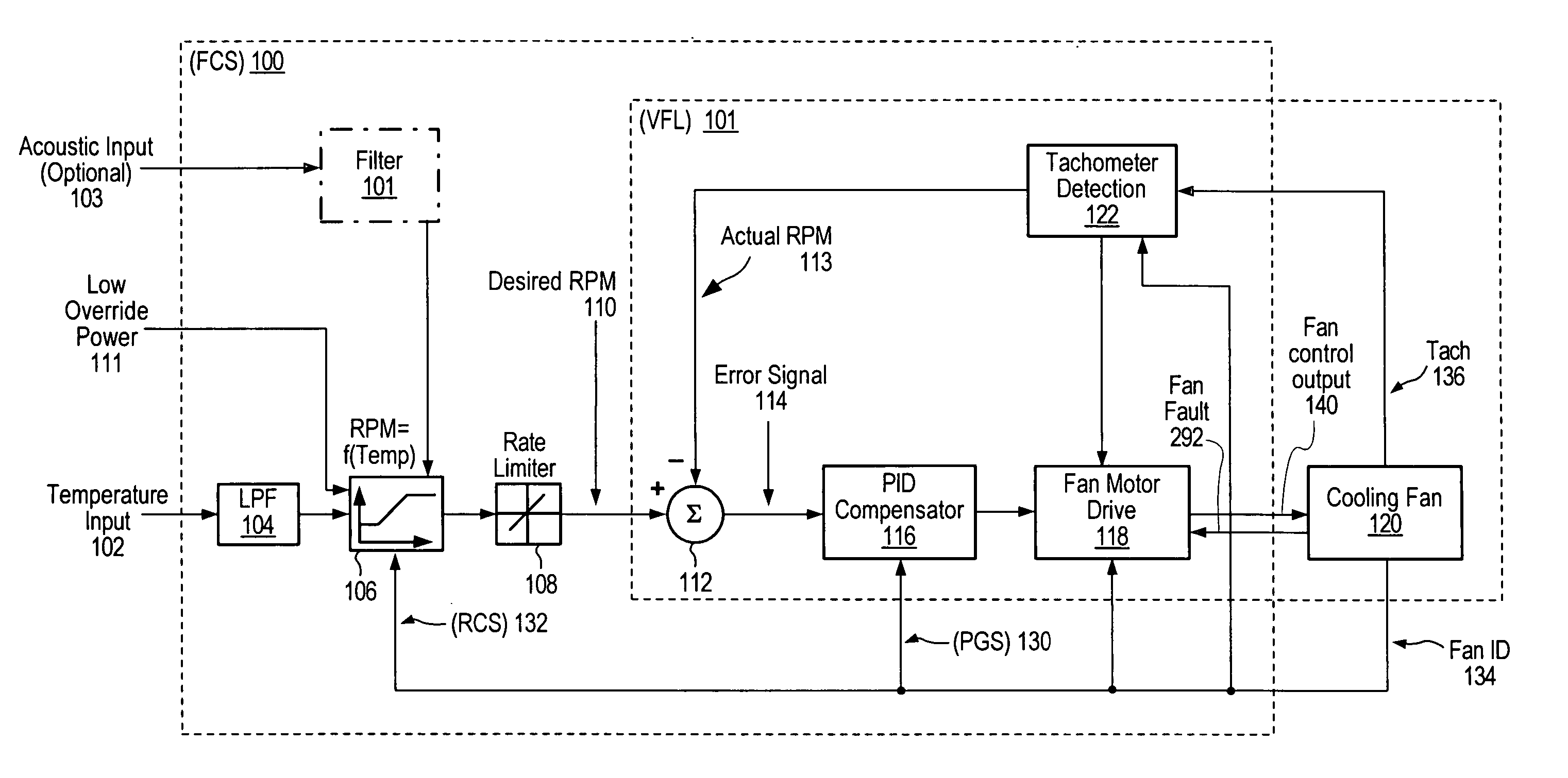
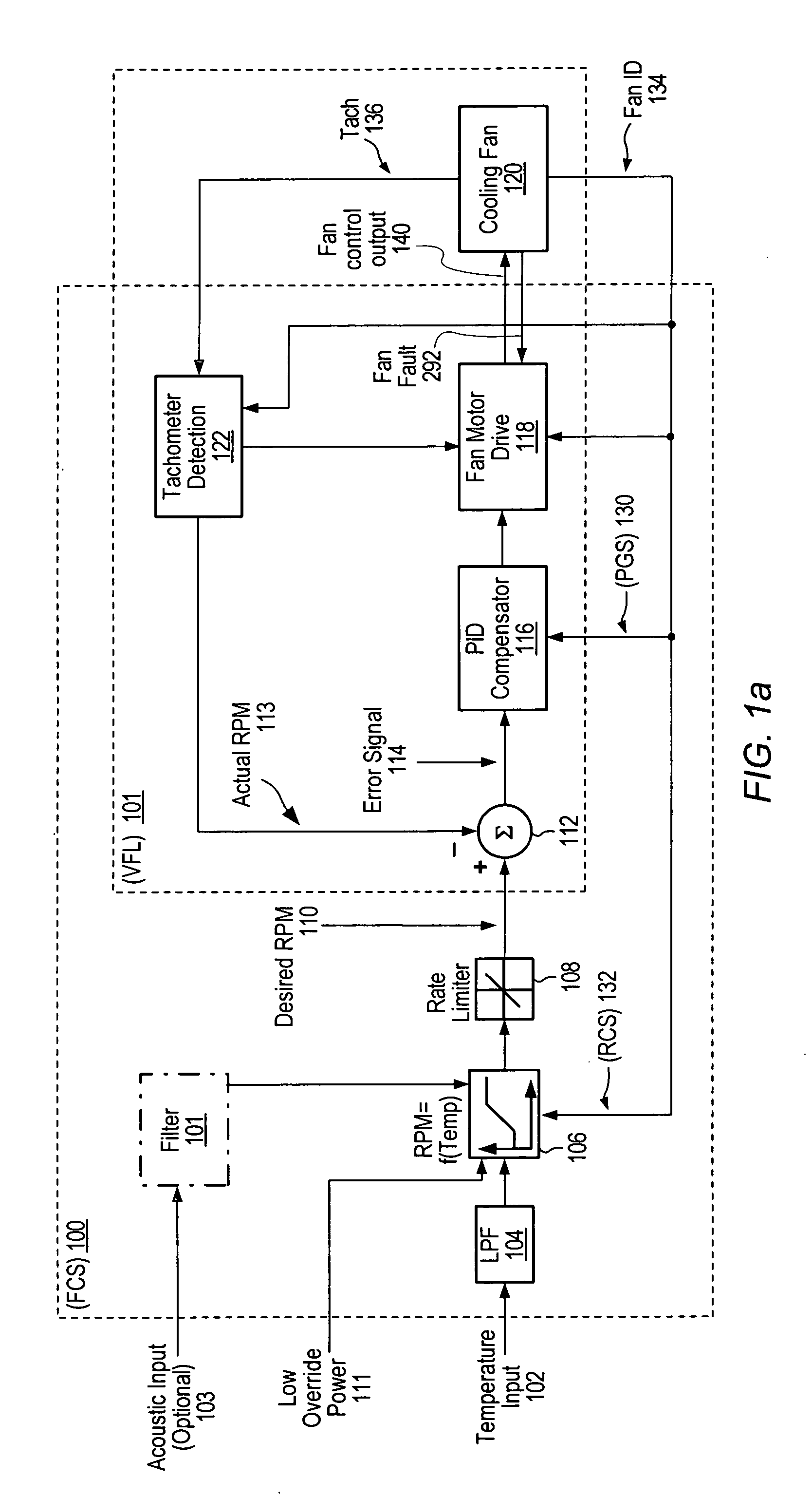
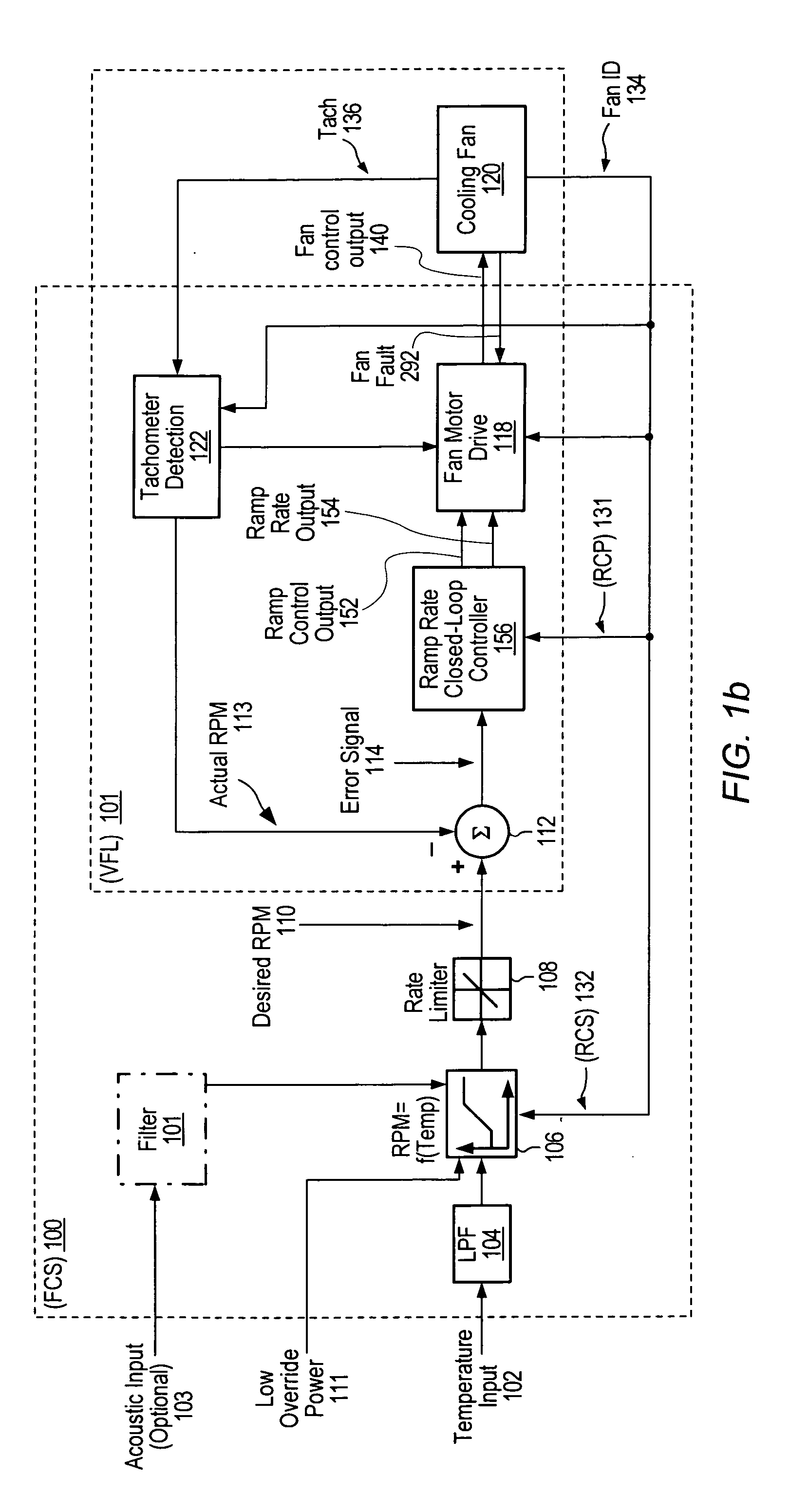
[0015] Performing fan control operations corresponding to the Temperature-versus-RPM function may be implemented using a microcontroller that may be configured in the fan controller. In one embodiment, a Fan ID feedback pin is provided, thereby making it possible to choose from a variety of several different fans on a given platform. The Fan ID feedback may also provide a mechanism to modify any of the respective parameters associated with the controller type used—for example the gain parameters of a PID compensator or ramp rate parameters of an RRCC—thereby creating an adaptive controller.
[0017] In one embodiment, the fan also comprises a Fan ID voltage pin. A fan ID signal through the Fan ID voltage pin may be provided as a feedback signal to the microcontroller, which may use the Fan ID signal upon system start-up to initialize the closed-loop velocity controller settings. For example, when a PID compensator is used, the Fan ID signal may be used to initialize the PID compensator gain settings and select the appropriate Temperature-versus-RPM function curve based on pre-determined values for the given fan issuing the Fan ID signal. In one set of embodiments, the fan control system may also facilitate Personal Computer (PC) manufacturers to have pre-engineered and embedded fan configurations in the BIOS of each platform. Thus, fans from different vendors may be changed at the factory without having to perform configuration programming. In one embodiment, the fan control algorithm obviates the need for a PWM command, thereby facilitating the removal of any associated circuitry from the fan and eliminating the need for commutation logic, thus reducing the cost of the fan.

Problems solved by technology

Typically, when considering a computer system from an overall systems perspective, 4-wire PWM-controlled cooling fans have unnecessary (i.e. redundant) built-in circuitry, which typically adds complexity and cost to the fans.
In addition, it is generally difficult to qualify different fans from multiple fan vendors when building a computer system due to the challenge in meeting the usually tight fan specifications.
Tight fan specifications generally add complexity and cost to cooling fans because the fan vendors must add circuitry in order to be within the specified tolerances.
Today's approaches to designing four-wire fan control systems typically do not address the issue of reducing the complexity of four-wire fans.
While simple proportional controllers have been introduced in some fan control systems, such controllers suffer from steady-state error, and the system response cannot be dampened to handle the wide variation of step-responses for fans from multiple fan vendors.

Method used


Image

  • Adaptive controller for PC cooling fans
  • Adaptive controller for PC cooling fans
  • Adaptive controller for PC cooling fans

Examples


Embodiment Construction

[0027] As used herein, a “controller” may mean a programmable microcontroller capable of executing code, or a hardware circuit configured to execute a specified function or set of functions and / or algorithms, or a combination of both. In some embodiments, a controller may mean a microcontroller adapted to execute a variety of specified algorithms, or a hardware circuit implementing a finite-state machine designed to perform the tasks required by the specified algorithms.

[0028]FIG. 1a shows a functional block diagram of one embodiment of a fan control system (FCS) 100. In this embodiment, actual temperature input 102 is sampled at the front end of FCS 100, and filtered with a low pass filter (LPF) 104 to smooth out noise and large temperature fluctuations. The filtered sampled temperature reading signal may then be provided as input to an RPM-versus-temperature profile function (RTPF) 106 that may generate and output a fan RPM value corresponding to the input temperature reading. In...


PUM


Abstract

A system and method for controlling a fan is disclosed. In one embodiment, a fan controller is integrated in silicon and uses an embedded microcontroller to implement a digital fan control algorithm. The microcontroller may continually monitor temperature and sample the speed of the controlled fan. The speed of the fan may be compared to RPM values fitted on a desired curve that is representative of the Temperature-versus-RPM function for the given controlled fan. The fan control algorithm may be based on a PID compensator or a Ramp Rate Closed-loop controller (RRCC), which may be operated to drive the fan to the desired speed. The fan may also provide a Fan ID feedback signal to the microcontroller, which may use the Fan ID feedback signal upon system start-up to initialize the PID compensator gain settings or the RRCC parameter settings, and select the appropriate Temperature-versus-RPM function curve based on pre-determined values for the given fan. Thus, fans from different vendors may be changed at the factory without having to perform configuration programming. The need for a PWM command may be obviated, thereby facilitating the removal of any associated circuitry from the given fan, and thus reducing the cost of the fan.

Description

PRIORITY CLAIM [0001] This application claims benefit of priority of provisional application Ser. No. 60 / 631,058 titled “Microcontroller-Based Integrated Adaptive PID Controller For PC Cooling Fans” and filed Nov. 24, 2004, which is hereby incorporated by reference as though fully and completely set forth herein.BACKGROUND OF THE INVENTION [0002] 1. Field of the Invention [0003] This invention relates to cooling equipment for electronic systems, e.g., fans, and more particularly, to controlling the rotational speed of a fan. [0004] 2. Description of the Related Art [0005] Fans are often used to evacuate warm air from enclosures in which electronic systems are contained. For example, most computer systems include one or more cooling fans to aid in circulating the air inside the enclosures and for maintaining the temperature inside the enclosures within an acceptable range. The increased airflow provided by fans typically aids in eliminating waste heat that may otherwise build up and ...

Claims


Application Information

Patent Timeline
IPC IPC(8): G05B11/42
CPCG05B13/024G05D23/1919
Inventor MURRAY, DAVID C.O'BRIEN, DENNISGOLDBERG, RANDY B.
Owner MICROCHIP TECH INC
Learn More