Fiber optic interferometric position sensor and measurement method thereof

a technology of position sensor and fiber optic, which is applied in the direction of interferometer, measurement device, instruments, etc., can solve the problem of interference signal plurality, and achieve the effect of high resolution and rapid measuremen

Active Publication Date: 2006-05-25
IND TECH RES INST
View PDF3 Cites 24 Cited by
  • Summary
  • Abstract
  • Description
  • Claims
  • Application Information

AI Technical Summary

Benefits of technology

[0017] In addition, the method for measuring the position of a measurement object according to the present invention provides a method for overcoming the drawbacks of the conventional fiber optic interferometers where not only the intensity of an interference signal is gradually decreased but also the waveform of the interference signal is gradually deformed as a gap is increased. The method for measuring the position of a measurement object according to the present invention incorporates a phase adjustment method, a bias correction method and an interpolation technique so that the fiber optic interferometric position sensor of the present invention characterized by a resolution of less than one-half wavelength of the light source and longer measurement distance is capable of rapidly measuring the displacement and the position of the measurement object. Hence, by adopting the method for measuring the position of a measurement object according to the present invention, the fiber optic interferometric position sensor of the present invention has a broader application scope than the prior capacitor sensors and can serve as a position sensor of a device having a tiny displacement and a high resolution, such as a piezoelectric displacement unit, a nanometer controlling unit or a micro-gage.

Problems solved by technology

The reference optical signals and the measurement signals interfere, resulting in a plurality of interference signals.

Method used


Image

  • Fiber optic interferometric position sensor and measurement method thereof
  • Fiber optic interferometric position sensor and measurement method thereof
  • Fiber optic interferometric position sensor and measurement method thereof

Examples


Embodiment Construction

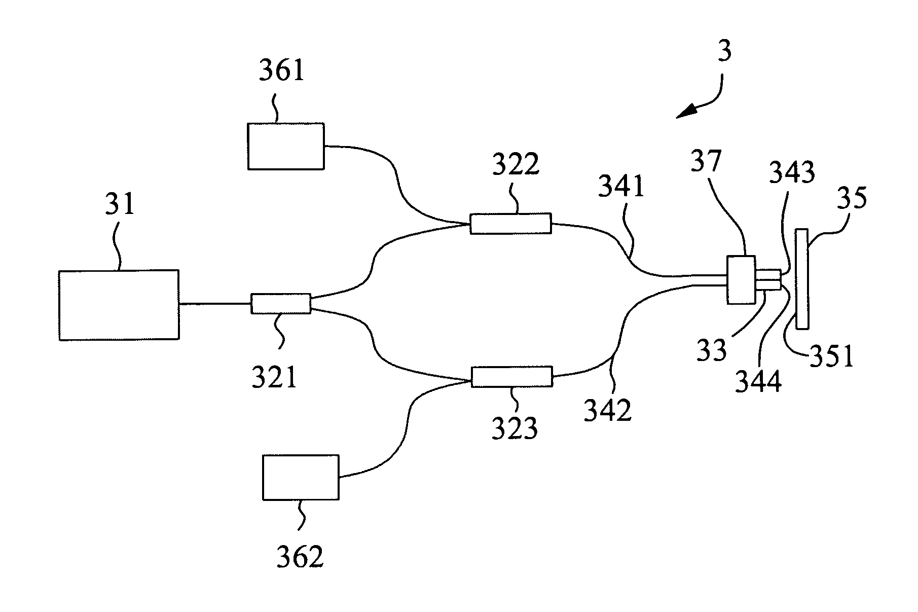
[0036] As shown in FIG. 3a, a fiber optic interferometric position sensor 3 of the present invention comprises a light source 31, a light-source fiber optic coupler 321, a first fiber optic coupler 322, a second fiber optic coupler 323, a first sensing fiber 341 and a second sensing fiber 342 both of which are fixed by means of an MT fiber optic array connector 33, a first photodetector 361 and a second photodetector 362. FIG. 3b is an enlarged diagram schematically illustrating the first sensing fiber 341 and the second sensing fiber 342 mounted on the surface 351 of a measurement object as shown in FIG. 3a, in which the provided MT fiber optic array connector 33 tilts a small angle α with respect to the normal line of the surface 351 of the measurement object by means of a micro-adjuster 37, the optical path length difference between the first sensing fiber 341 and the second sensing fiber 342 having a space ε from the first sensing fiber 341 that can be expressed as 2εα.

[0037] T...


PUM


Abstract

A fiber optic interferometric position sensor and measurement method thereof suitable for determining the moving direction of a measurement object in an environment of high electric or magnetic field strengths are disclosed. The fiber optic interferometric position sensor comprises at least one light source, a plurality of fiber optic couplers, a plurality of sensing fibers and a plurality of photodetectors. The fiber optic couplers are connected to the at least one light source, the photodetectors, and the sensing fibers, respectively. The measurement method comprises: providing a fiber optic interferometric position sensor and a measurement object, obtaining two initial signals having a 90-degree phase difference therebetween, obtaining two measured signals, correcting the measured signals by a bias correction method, obtaining the phase value from the two measured signals by an electronic interpolation technique, and obtaining the position of the measurement object after computation by using the phase value.

Description

BACKGROUND OF THE INVENTION [0001] 1. Field of the Invention [0002] The present invention relates to a fiber optic interferometric position sensor and measurement method thereof, and more particularly, to a fiber optic interferometric position sensor and measurement method thereof suitable for determining the moving direction of a measurement object in an environment of high electric or magnetic field strengths. [0003] 2. Description of Related Art [0004] At present, the industry primarily adopts a capacitor sensor to serve as a sub-nanometer scale position sensor. However, the capacitor sensor has some drawbacks, as immediately described below, which limit its application scope. At first, if a high electric or magnetic field strength is applied to the neighborhood of the probe of the capacitor sensor during measurement, the reading obtained by the capacitor sensor will be affected. As a result, an error occurs in this measurement. Next, in order to apply the principle of the capaci...

Claims


Application Information

Patent Timeline
Patent Type & Authority Applications(United States)
IPC IPC(8): G01B9/02
CPCG01D5/35303G01B9/02019G01B9/02027G01B9/02057G01B9/02083G01B2290/45
Inventor TAI, HUNG-MINGCHOU, JUNG-TSUNGCHENG, KAI-YUHUANG, HUANG-CHIHUANG, CHIUNG-HUEIYEH, CHING-MING
Owner IND TECH RES INST
Why Eureka
Try Eureka