Variable stator vane bushings and washers

a stator vane bushing and washer technology, applied in the direction of machines/engines, stators, liquid fuel engines, etc., can solve the problems of different temperature limitations, stresses and cyclic vibrations, and the material solution of one system may not be an effective material solution for a different mechanical system design. , to achieve the effect of reducing overhaul costs and facilitating withstand

Inactive Publication Date: 2006-05-25
GENERAL ELECTRIC CO
View PDF19 Cites 49 Cited by
  • Summary
  • Abstract
  • Description
  • Claims
  • Application Information

AI Technical Summary

Benefits of technology

[0019] Yet another advantage of the lubricant coating, according to an embodiment of the present invention, is that the wear coating and antifriction coating combination reduces wear and maintains desirable tribological properties in high altitude atmospheres having little or no water vapor.
[0020] Yet another advantage of the lubricant coating, according to an embodiment of the present invention, is that the variable stator vane assembly provides an efficiency improvement in the turbine engine while reducing overhaul costs caused by wear resulting from metal on metal contact between the stator casing surface and the stator vane surface.
[0021] Yet another advantage of the lubricant coating, according to an embodiment of the present invention, is that the materials used in the variable stator vane assembly of the present invention, including the antifriction coating, can readily withstand the higher temperatures of operation utilized in current advanced engine designs. The materials used in the antifriction coating of the present invention can be utilized at temperatures greater than about 1000° F. (538° C.), including operational temperatures of up to about 1200° F. (649° C.), without significant deterioration due to the combined effects of temperature, vibration, and high altitude atmosphere.
[0022] Yet another advantage of the lubricant coating of an embodiment of the present invention is that the antifriction coating is capable of maintaining lubricity in applications that rub in a reciprocating motion.
[0023] Another advantage of the lubricant coating, according to an embodiment of the present invention, is that the antifriction coating is resilient and regenerates in areas where the antifriction coating is rubbed thin or cleaned off the wear surface.
[0024] Yet another advantage of an embodiment of the present invention is that the method provides an inexpensive fabrication method that provides a seal tube at near-net shape, requiring few or no subsequent processing steps prior to installation into the bearing system.

Problems solved by technology

Each design is subjected to different temperature limitations, stresses and cyclic vibrations.
Thus a materials solution for one system may not be an effective materials solution for a different mechanical system design.

Method used


Image

  • Variable stator vane bushings and washers
  • Variable stator vane bushings and washers
  • Variable stator vane bushings and washers

Examples


Embodiment Construction

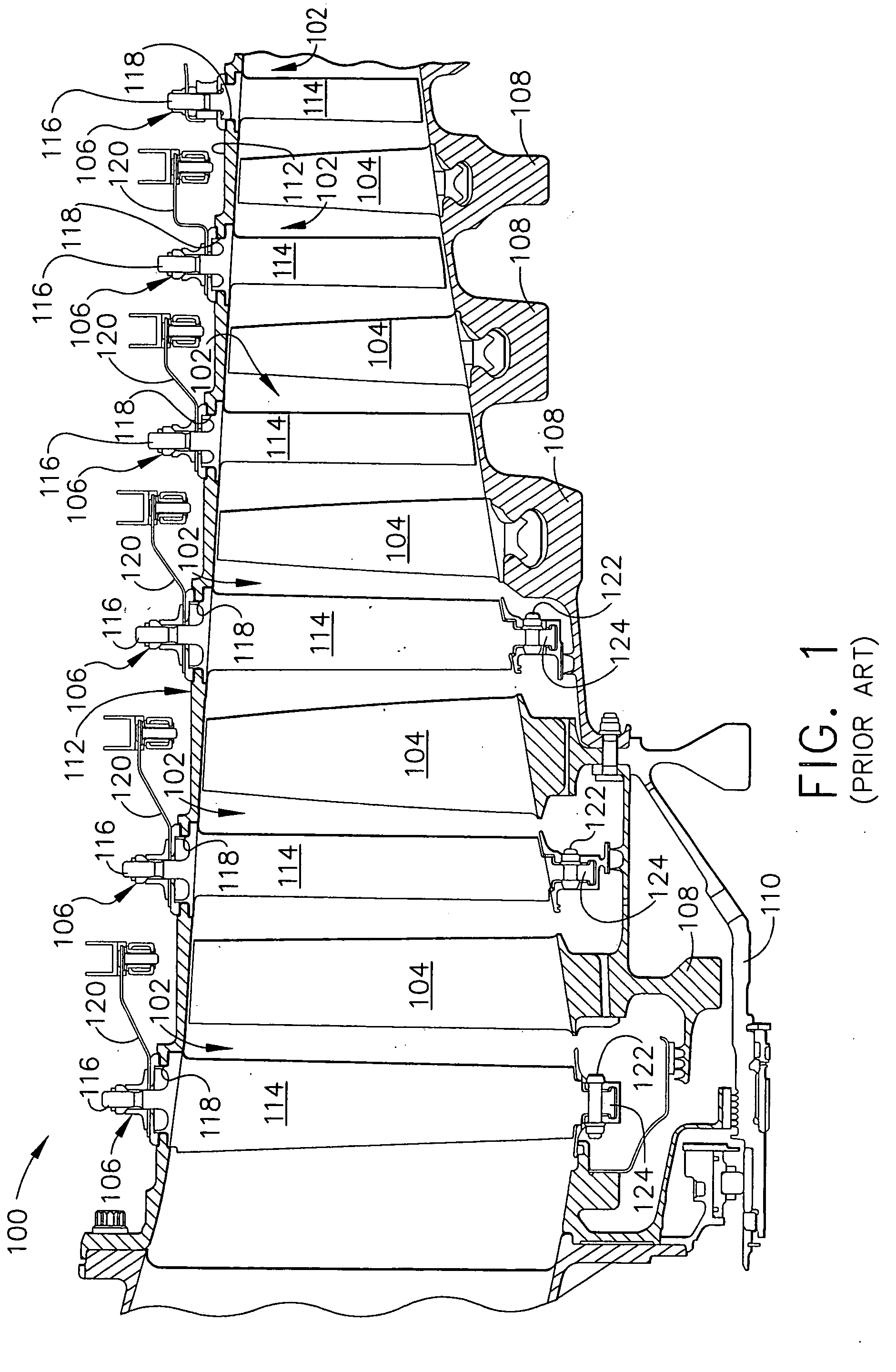
[0040]FIG. 1 is a schematic view of a section of a known high-pressure compressor 100 for a typical turbine engine (not shown). Compressor 100 includes a plurality of stages 102, and each stage 102 includes a row of rotor blades 104 and a row of variable stator vane assemblies 106. Rotor blades 104 are typically supported by rotor disks 108, which are connected to a rotor shaft 110. Rotor shaft 110 is a high-pressure shaft that is also connected to a high-pressure turbine (not shown). Rotor shaft 110 is surrounded by a stator casing 112 that supports variable stator vane assemblies 106.

[0041] Each variable stator vane assembly 106 includes a variable vane 114 and a vane stem 116. Vane stem 116 protrudes through an opening 118 in casing 112. Variable vane assemblies 106 further include a lever arm 120 extending from variable vane 114 that is utilized to rotate variable vanes 114. The orientation of variable vanes 114 relative to the flow path through compressor 100 control airflow t...


PUM

PropertyMeasurementUnit
thicknessaaaaaaaaaa
temperaturesaaaaaaaaaa
temperatureaaaaaaaaaa

Abstract

A variable stator vane assembly for use in a compressor section of a turbine engine having a plurality of movable metallic stator vanes and a method for making a variable stator vane assembly. The variable stator vane assembly includes a metallic stator casing supporting the vanes and a bushing system positioned between the stator vanes and the stator casings. The bushing system includes a bushing fabricated from a material selected from the group consisting of metal, ceramic or combinations thereof. The variable stator vane further including a titanium nitride wear coating disposed on a surface of the vanes in contact with the bushing system.

Description

CROSS-REFERENCE TO RELATED APPLICATIONS [0001] This application is a Continuation-in-Part of U.S. patent application Ser. No. 11 / 207,921, which is a Continuation-in-Part of U.S. patent application Ser. No. 10 / 445,428, filed May 27, 2003, each of which is herein incorporated by reference in their entirety.FIELD OF THE INVENTION [0002] This invention relates generally to components of gas turbine engines and, in particular, to variable stator vane bushings and washers systems used in the compressor section of the engine. BACKGROUND OF THE INVENTION [0003] In gas turbine engines, for example, aircraft engines, air is drawn into the front of the engine, compressed by a shaft-mounted rotary compressor, and mixed with fuel. The mixture is burned, and the hot exhaust gases are passed through a turbine mounted on a shaft. The flow of gas turns the turbine, which turns the shaft and drives the compressor. The hot exhaust gases flow from the back of the engine, providing thrust that propels t...

Claims


Application Information

Patent Timeline
Patent Type & Authority Applications(United States)
IPC IPC(8): F04D29/56
CPCF01D17/162F04D29/023F04D29/563Y02T50/672F05D2230/90F05D2300/611F05D2300/2284Y02T50/60
Inventor BRUCE, ROBERT W.
Owner GENERAL ELECTRIC CO
Why Eureka
Try Eureka