Wafer alignment method

Active Publication Date: 2006-05-25
KEY FOUNDRY CO LTD
View PDF1 Cites 10 Cited by
  • Summary
  • Abstract
  • Description
  • Claims
  • Application Information

AI Technical Summary

Benefits of technology

[0011] Accordingly, the present invention has been made in view of the above problems, and it is an object of the present invention to provide a wafer alignment method in which misalignment of semiconductor substrates can be prevented when multi-layer semiconductor substrates in which semiconductor devices are formed are stacked in an aligned manner.

Problems solved by technology

If the semiconductor substrates respectively provided in the memory device and the logic element are stacked, however, a misalignment phenomenon frequently occurs.
This makes difficult electrical connection of the semiconductor substrate in which the memory device is provided and the semiconductor substrate in which the logic element is provided.

Method used


Image

  • Wafer alignment method
  • Wafer alignment method
  • Wafer alignment method

Examples


Embodiment Construction

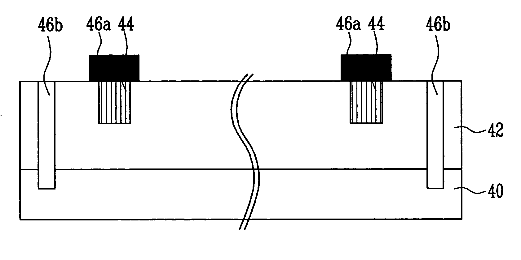
[0017] Now, the preferred embodiments according to the present invention will be described with reference to the accompanying drawings. Since preferred embodiments are provided for the purpose that the ordinary skilled in the art are able to understand the present invention, they may be modified in various manners and the scope of the present invention is not limited by the preferred embodiments described later. Meanwhile, in case where it is described that one film is “on” the other film or a semiconductor substrate, the one film may directly contact the other film or the semiconductor substrate. Or, a third film may be intervened between the one film and the other film or the semiconductor substrate. Furthermore, in the drawing, the thickness and size of each layer are exaggerated for convenience of explanation and clarity. Like reference numerals are used to identify the same or similar parts.

[0018] FIGS. 2 to 6 are cross-sectional views for explaining a wafer alignment method a...


PUM


Abstract

The present invention relates to a wafer alignment method. The wafer alignment method includes the steps of forming first bonding pads and first wafer alignment marks of a convex shape on predetermined regions of a first semiconductor substrate in which a first device is formed, forming second bonding pads on predetermined regions of a second semiconductor substrate in which a second device is formed so that they correspond to the first bonding pads, and forming second wafer alignment marks of a hall shape on the predetermined regions of the second semiconductor substrate so that they correspond to the wafer alignment marks of the convex shape, disposing a rear surface of the second semiconductor substrate upwardly, so that the first bonding pads of the first semiconductor substrate and the second bonding pads of the second semiconductor substrate correspond to each other, polishing the rear surface of the second semiconductor substrate to form holes of the second wafer alignment marks through which X-rays to be projected later penetrate, aligning the first semiconductor substrate and the second semiconductor substrate so that the X-rays projected from the X-ray projector penetrate the second wafer alignment marks of the second semiconductor substrate and then reach the wafer alignment marks of the first semiconductor substrate through a X-ray sensing device, which has an X-ray projector and an X-ray detector and is adjacent to the rear surface of the second semiconductor substrate, and performing a thermal process on the first semiconductor substrate and the second semiconductor substrate, which are aligned, to electrically connect the first bonding pads and the second bonding pads.

Description

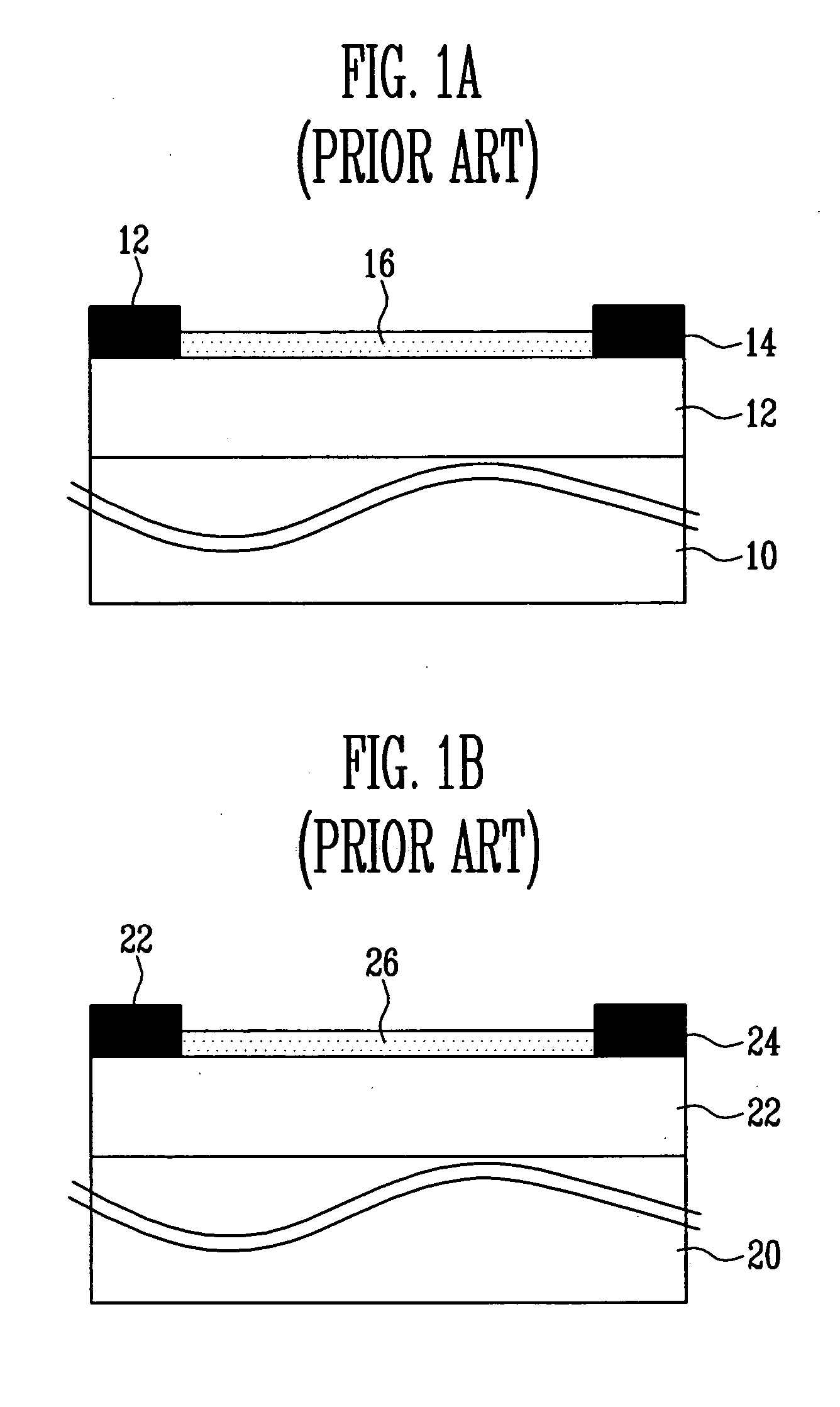
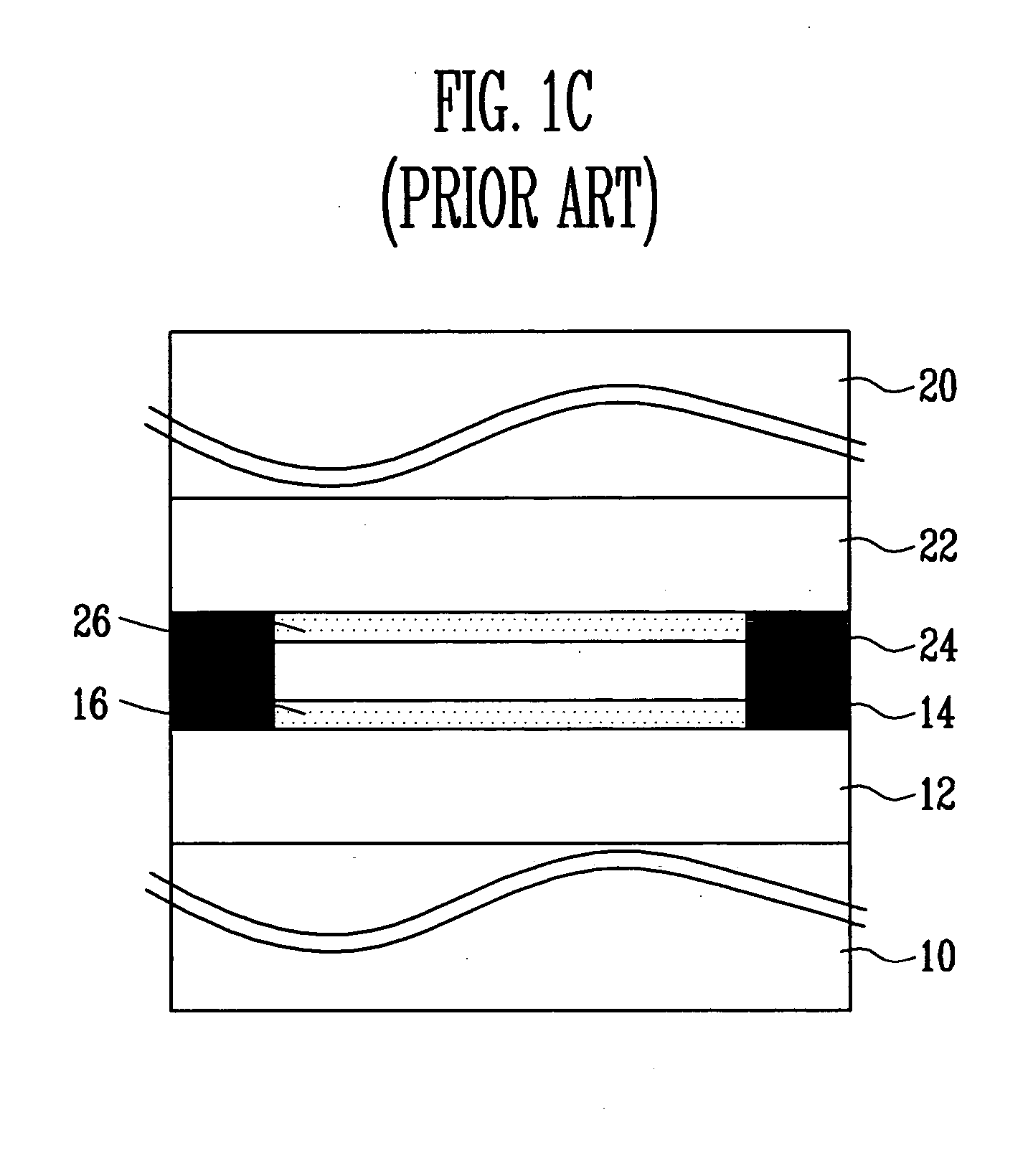
BACKGROUND [0001] 1. Field of the Invention [0002] The present invention relates to a method of manufacturing semiconductor devices, and more specifically, to a wafer alignment method. [0003] 2. Discussion of Related Art [0004] Recently, semiconductor devices used for embedded memory in the field of system ICs or SOC (System On Chip) have memory devices, such as DRAM, SRAM, flash memory and EEPROM, and logic elements for field applications formed on a semiconductor substrate. There is a need for manufacturing technology of semiconductor devices, wherein different elements are formed in two or more semiconductor substrates and the substrates are then stacked. [0005]FIGS. 1a to 1c are cross-sectional views for explaining a conventional wafer alignment method. [0006] Referring to FIG. 1a, an interlayer insulating film 12 is formed on a semiconductor substrate 10 having a memory device formed in. While a final metal line is formed on the interlayer insulating film 12, bonding pads 14 of...

Claims


Application Information

Patent Timeline
IPC IPC(8): H01L21/44
CPCH01L23/544H01L24/81H01L25/50H01L2223/5442H01L2223/54426H01L2223/54473H01L2223/5448H01L2224/81121H01L2224/81801H01L2225/06513H01L2225/06593H01L2924/14H01L2924/19041H01L2924/01006H01L2924/01033Y10S438/975H01L24/82
Inventor HAN, IL SEOK
Owner KEY FOUNDRY CO LTD
Why Eureka
Try Eureka