
Wireless communication circuit, wireless communication circuit system, and wireless communication apparatus

Inactive Publication Date: 2006-05-25
PANASONIC CORP
View PDF4 Cites 2 Cited by
  • Summary
  • Abstract
  • Description
  • Claims
  • Application Information

AI Technical Summary

Benefits of technology

[0019] It is therefore an object of the present invention to provide a wireless communication circuit, a wireless communication circuit system, and a wireless communication apparatus, in which the number of parts can be reduced.
[0020] It is another object of the present invention to provide the wireless communication circuit system and the wireless communication apparatus, in which the number of terminals of a controller can be reduced.
[0024] According to this configuration, one high pass filter can be shared for filtering the tone signal included in the output signal of the received signal detector circuit, and filtering the frequency component of the tone signal included in the audio signal inputted from the microphone. As a result, one high pass filter can be eliminated, thereby making it possible to achieve a reduction of the number of parts.
[0029] Specifically, the pulse signal with the same frequency as that of the tone signal desired to be outputted is outputted from the controller, and the switches are provided anterior and posterior the low pass filter of the subsequent stage of the received signal detector circuit, respectively, so that the pulse signal is inputted into the low pass filter in transmission, thereby allowing to generate the tone signal close to a sine wave.
[0030] According to this configuration, the low pass filter used for the frequency discrimination of the tone signal included in the output signal of the received signal detector circuit is utilized, and the pulse signal outputted from the controller is passed through the low pass filter, so that the higher harmonic is filtered from the pulse signal, allowing to generate the tone signal. For that reason, what is necessary is to output the pulse signal having the same fundamental frequency as that of the tone signal from the controller. Accordingly, that makes it possible to achieve a reduction of the number of terminals of the controller and an elimination of the number of resistors that are required for the tone signal generation.
[0031] As described above, according to the present invention, one high pass filter can be eliminated, and the reduction of the number of terminals of the controller and the elimination of the number of the resistors that are required for tone signal generation can be achieved, thereby making it possible to easily achieve a cost reduction and a miniaturization of the wireless communication apparatus.

Problems solved by technology

The high pass filter shown in FIG. 6, however, requires a large number of parts.
Further, when the tone generating circuit 11 shown in FIG. 7 has been used, there has been a problem that the number of terminals of the controller 13 has been increased.

Method used


Image

  • Wireless communication circuit, wireless communication circuit system, and wireless communication apparatus
  • Wireless communication circuit, wireless communication circuit system, and wireless communication apparatus
  • Wireless communication circuit, wireless communication circuit system, and wireless communication apparatus

Examples


first embodiment

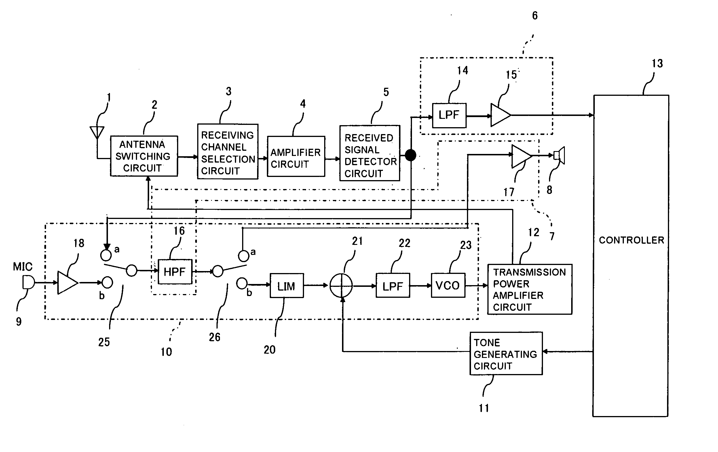
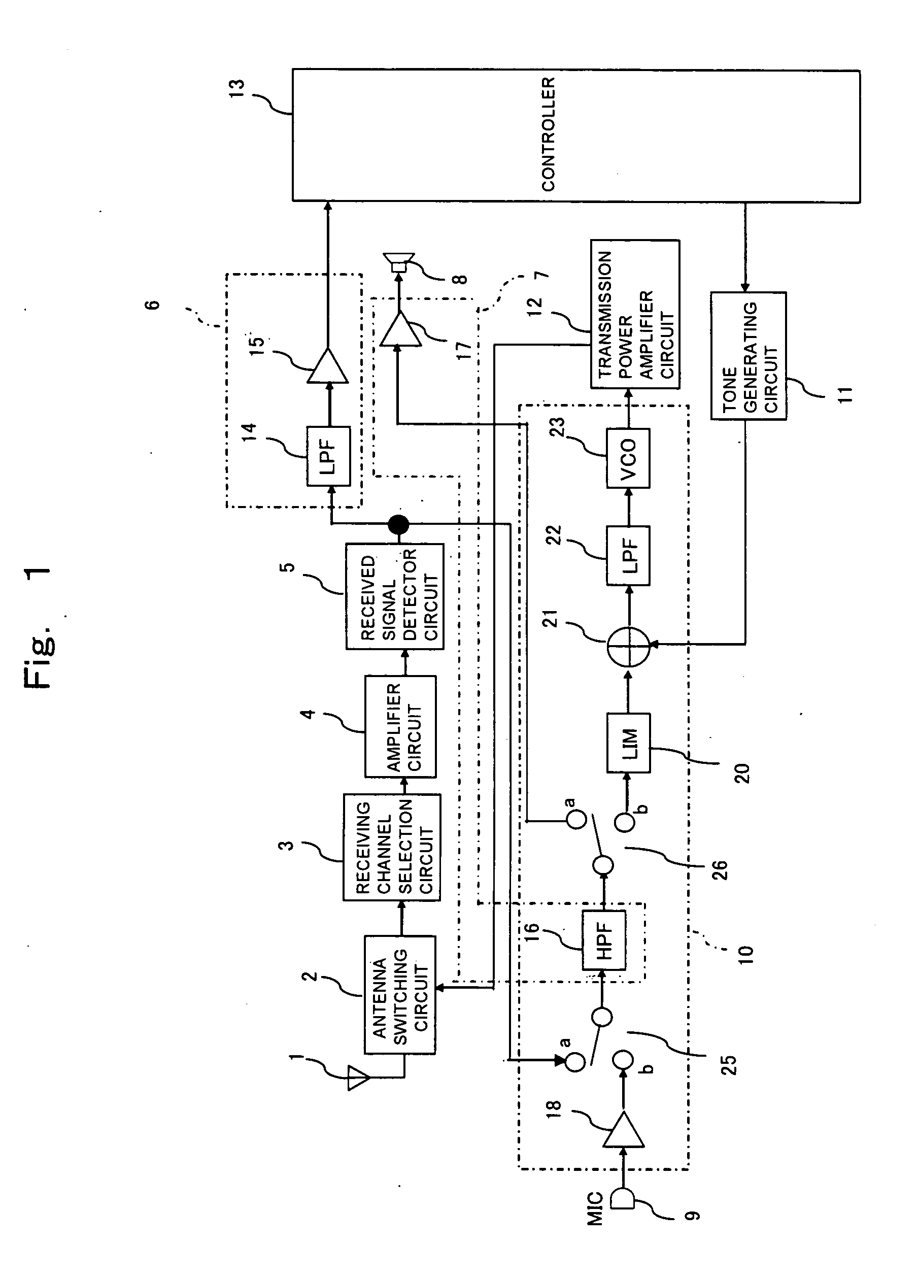
[0041] Hereinafter, referring to the drawings, a wireless communication apparatus according to a first embodiment of the present invention will be explained. The same symbol is given to a member corresponding to the member explained in FIG. 4, and detailed description will be omitted.

[0042]FIG. 1 shows a circuit configuration of the wireless communication apparatus for explaining the first embodiment of the present invention. In FIG. 1, reference numeral 1 represents an antenna; reference numeral 2, an antenna switching circuit for switching a reception signal and a transmission signal; reference numeral 3, a receiving channel selection circuit for passing a received signal to a subsequent stage when the received signal is a preset frequency; reference numeral 4, an amplifier circuit for amplifying the received signal; reference numeral 5, a received signal detector circuit such as an FM demodulation or the like for demodulating the received signal; reference numeral 6, a tone freq...

second embodiment

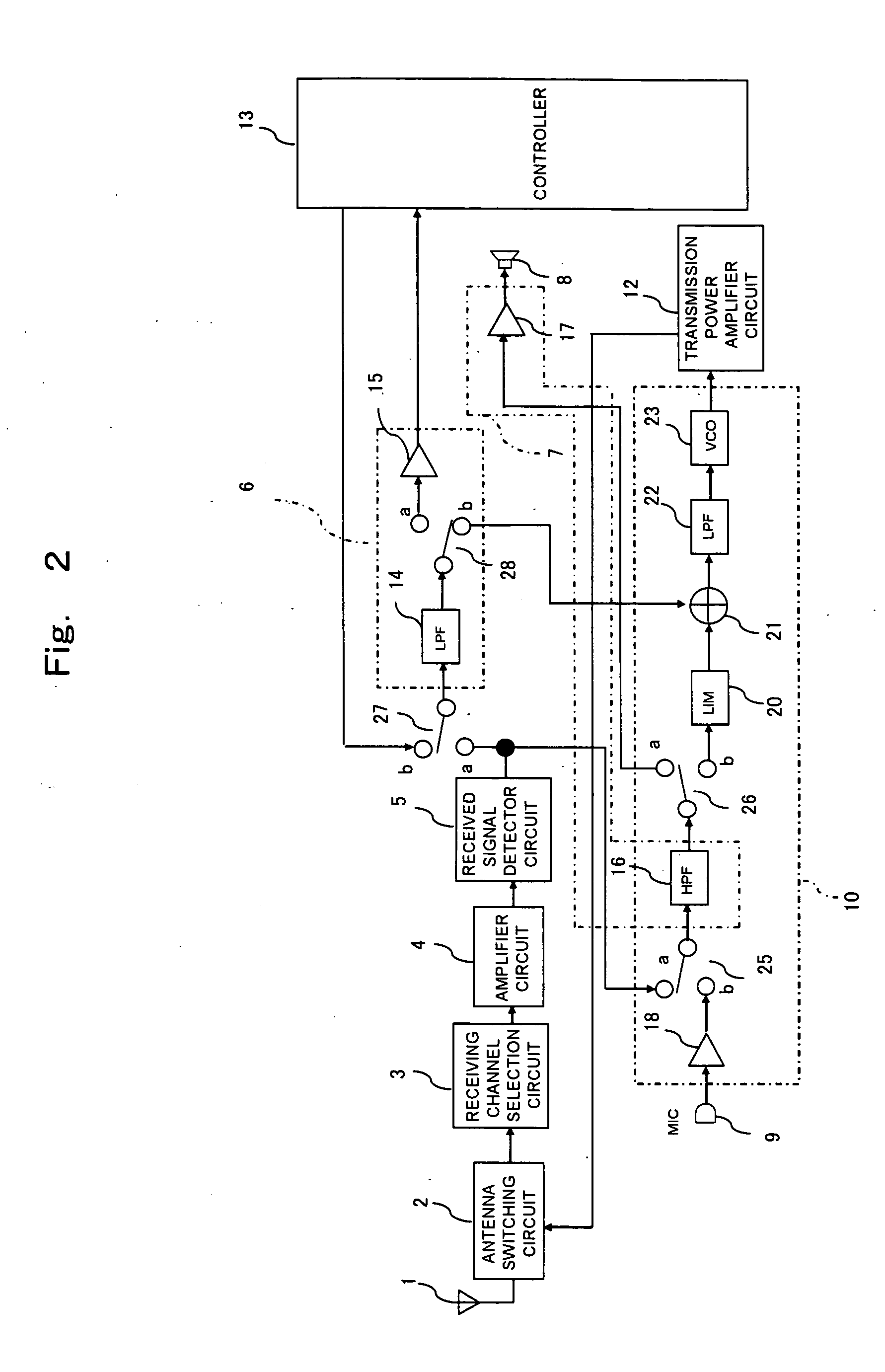
[0053] Hereinafter, referring to the drawings, a wireless communication apparatus according to a second embodiment of the present invention will be explained. The same symbol is given to a member corresponding to the member explained in FIGS. 1 and 4, and detailed description will be omitted.

[0054]FIG. 2 shows a circuit configuration of the wireless communication apparatus for explaining the second embodiment of the present invention. In FIG. 2, reference numeral 27 represents a switch for selecting whether the pulse signal outputted from the controller 13 is inputted into the low pass filter 14, or the output signal of the received signal detector circuit 5 is inputted into the low pass filter 14. Reference numeral 28 represents a switch for selecting whether the output signal of the low pass filter 14 is transmitted to the comparator 15, or to the adding circuit 21.

[0055] According to this embodiment, the tone generating circuit 11 composed of the resistors as shown in the prior...


PUM


Abstract

A first switch is provided between a received signal detector circuit and an amplifier circuit of a microphone signal, and a high pass filter, and a second switch is provided between a high pass filter, and a signal amplifier circuit in a preceding stage of a loudspeaker and an amplitude limiting circuit of a transmission signal. The high pass filter is thereby shared for transmission and reception. The high pass filter filters a tone signal from an output signal of the received signal detector circuit to extract an audio signal in reception. The high pass filter also filters a frequency component of the tone signal included in the audio signal inputted from the microphone in transmission.

Description

BACKGROUND OF THE INVENTION [0001] 1. Field of the Invention [0002] The present inventions relates generally to a wireless communication apparatus, such as a transceiver provided with a tone signal generating function and a frequency discriminating function of the tone signal, and a wireless communication circuit and a wireless communication circuit system composing the same, and particularly to a method of reducing the number of parts. [0003] 2. Description of the Prior Art [0004] As a prior art of a wireless communication apparatus, such as a transceiver provided with a tone signal generating function and a frequency discriminating function of the tone signal, a configuration described in, for example patent document 1 will be included as an example. [0005]FIG. 4 is a block diagram showing a configuration of a wireless communication apparatus according to the prior art. [0006] In FIG. 4, reference numeral 1 represents an antenna; reference numeral 2, an antenna switching circuit f...

Claims


Application Information

Patent Timeline
IPC IPC(8): H04M1/00
CPCH04B1/44
Inventor SATOU, KAZUTOSHI
Owner PANASONIC CORP
Learn More