Portable hydrogen generator and fuel cell system

a hydrogen generator and fuel cell technology, applied in the direction of electrochemical generators, chemical/physical processes, chemical apparatus and processes, etc., can solve the problems of high cost, potential explosion danger, and lack of an acceptable lightweight and safe hydrogen storage and supply system

Inactive Publication Date: 2006-06-01
NANOTEK INSTR
View PDF9 Cites 17 Cited by
  • Summary
  • Abstract
  • Description
  • Claims
  • Application Information

AI Technical Summary

Benefits of technology

[0017] The hydrogen generator has a mechanism that permits relative motions between the two discs for the purpose of adjusting the catalyst-fuel contact areas and, hence, the hydrogen gas production rate. The major features of this new design include simplicity, compac

Problems solved by technology

A major barrier to a more widespread utilization of hydrogen fuel cells for powering vehicles or microelectronic devices is the lack of an acceptable lightweight and safe hydrogen storage and supply system.
However, these technologies still have several major drawbacks to overcome before they can be more fully implemented: (1) low H2 storage capacity, (2) difficulty in storing and releasing H2 at a controlled rate (normally requiring a high temperature to release and a high pressure to store hydrogen), (3) high costs, (4) potential explosion danger, and (5) system being bulky, heavy and non-portable.
The above prior-art hydrogen generation systems are still very complex, heavy, and/or bulky.
Although some of these systems appear to be portable, they are too bulky and heavy to be used for feeding hydrogen fuel to small fuel cel

Method used


Image

  • Portable hydrogen generator and fuel cell system
  • Portable hydrogen generator and fuel cell system
  • Portable hydrogen generator and fuel cell system

Examples


Embodiment Construction

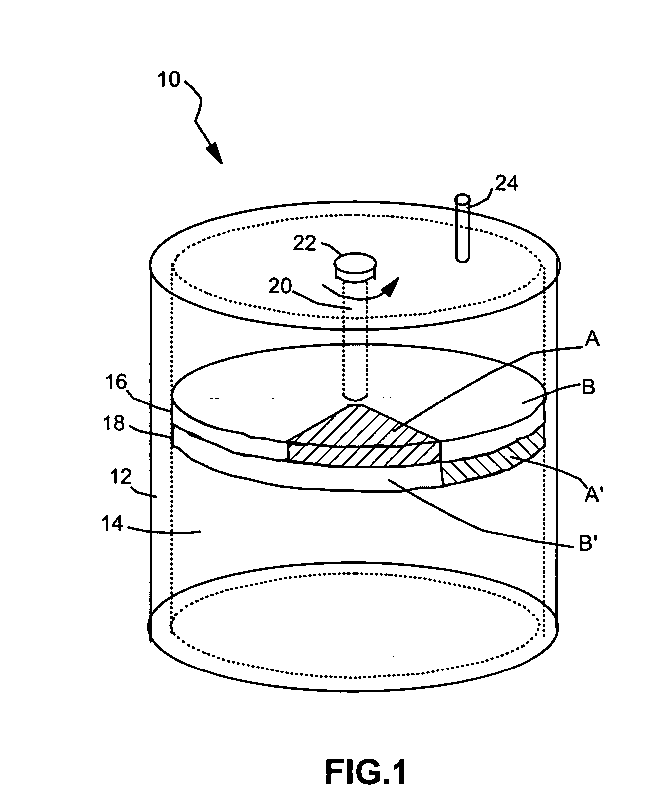
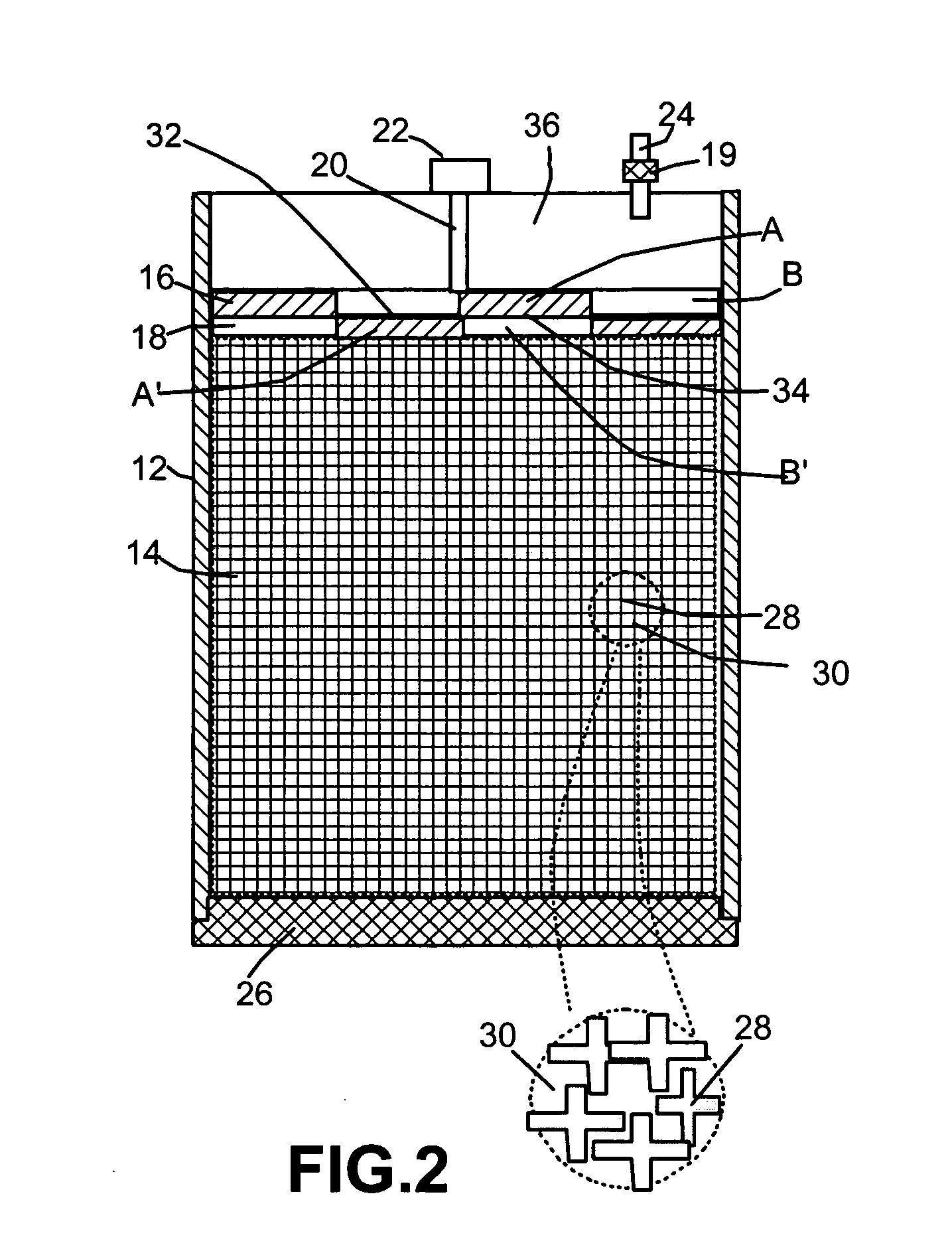
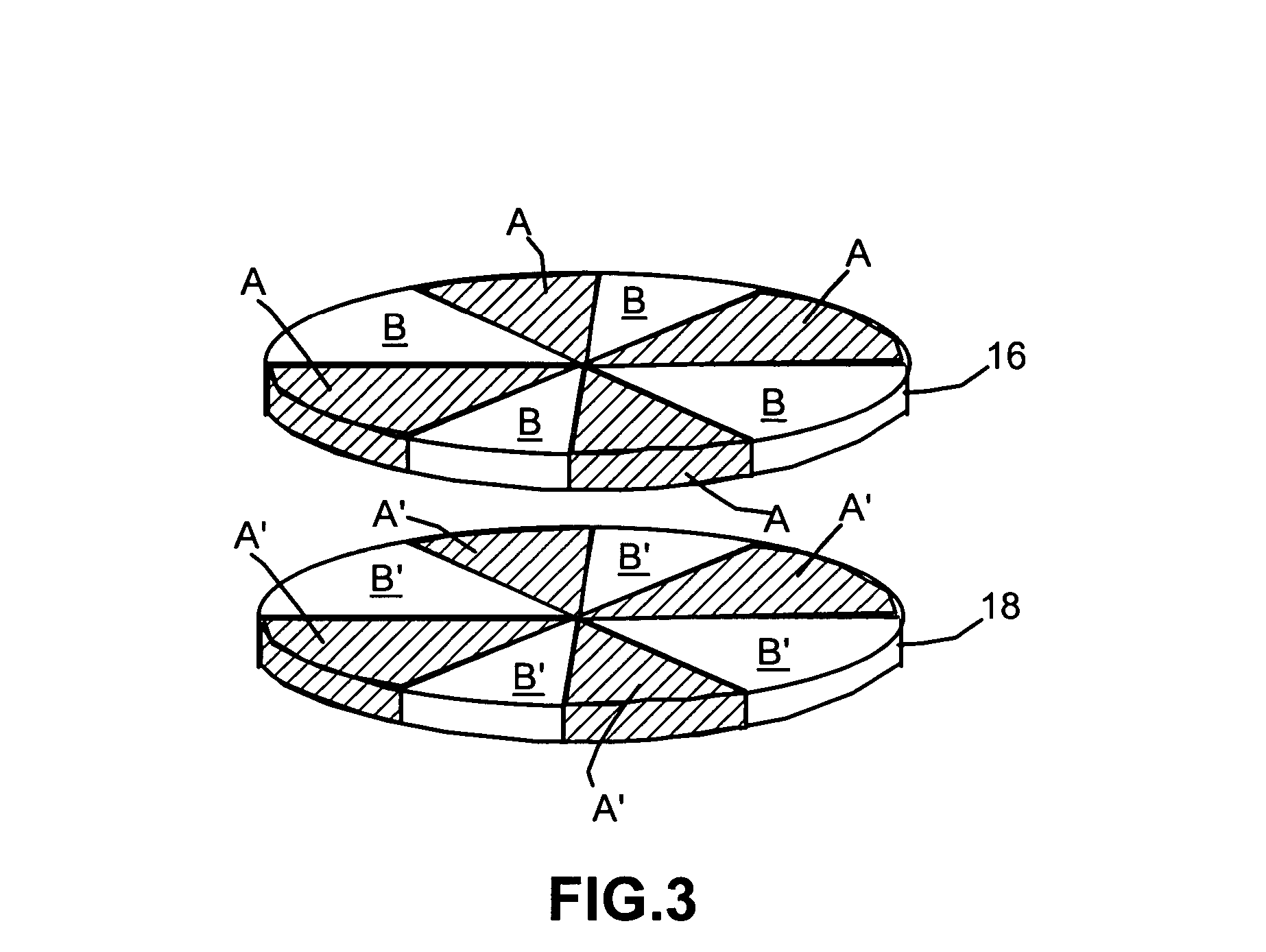
[0029] The presently invented portable hydrogen gas generator is based on a class of metal hydride solution fuels that have the following features: The water solution of a metal hydride, particularly a complex metal hydride such as NaBH4, LiBH4, KBH4, Al(BH4)3, TiFeH2, or Pd2H, is quite stable. Some form of catalyst is needed in order for the hydride-water reaction to proceed at an appreciable rate. As a consequence, this reaction is highly controllable and this is one of the great advantages of this system. For example, if NaBH4 is used as the metal hydride component, the reaction of NaBH4 with water (according to Eq.(1)) does not normally proceed spontaneously:

NaBH4+2H2O→NaBO2+4H2(g)   (1)

[0030] A small amount of basic solution such as NaOH or KOH could make the solution of NaBH4+2H2O even more stable. The present invention provides a simple and reliable way of bringing a catalyst into contact with such a fuel solution to produce hydrogen at a controlled, but variable rate in re...


PUM


Abstract

A hydrogen generator apparatus that delivers a hydrogen stream at a controlled rate to a fuel cell. The apparatus comprises a fuel tank, a wicking material in the fuel tank, a fluid retained in the wicking material, a first disc bounding the wicking material and comprising a hydrophilic membrane for receiving the fluid from the wicking material by a wicking pressure to form a fluid-wetted surface, a second disc having a porous surface area with the second disc being in contact with the first disc with the two discs moveable relative to each other, a catalyst on the porous surface to form a catalyst-coated surface, and hydrogen generated by hydrolyzation of the fluid contacting the catalyst due to a relative motion between the first disc and the second disc. Major features of this apparatus include simplicity, compactness and portability, hydrogen production rate adjustability, reliability, the ability to operate in any orientation and, in one preferred embodiment, a feedback mechanism to automatically maintain a constant pressure supply of hydrogen or constant hydrogen flow rate. The invention also provides an actively or passively controlled power source featuring such a hydrogen generator.

Description

[0001] The present invention is a result of a research project supported by the NSF SBIR-STTR Program. The US Government has certain rights on this invention.FIELD OF THE INVENTION [0002] This invention relates to a portable hydrogen generator and an electric power source comprising such a hydrogen generator and a fuel cell assembly. BACKGROUND OF THE INVENTION [0003] A major barrier to a more widespread utilization of hydrogen fuel cells for powering vehicles or microelectronic devices is the lack of an acceptable lightweight and safe hydrogen storage and supply system. Six conventional approaches to hydrogen storage and supply are currently in use: (a) liquid hydrogen, (b) compressed gas, (c) cryo-adsorption, (d) metal hydride, (e) nano-scale carbon materials, and (f) hollow micro-spheres. However, these technologies still have several major drawbacks to overcome before they can be more fully implemented: (1) low H2 storage capacity, (2) difficulty in storing and releasing H2 at a...

Claims


Application Information

Patent Timeline
IPC IPC(8): B01J7/00
CPCB01J7/02C01B3/065C01B2203/066H01M8/04089H01M8/04201H01M8/04216H01M8/065Y02E60/362Y02E60/50Y02E60/36
Inventor YANG, LAIXIAGUO, JIUSHENGHUANG, WEN CHIANGJANG, BOR Z.
Owner NANOTEK INSTR
Why Eureka
Try Eureka