Microfluidic device and method for improved sample handling

a microfluidic device and sample technology, applied in fluid pressure measurement, liquid/fluent solid measurement, peptide measurement, etc., can solve the problems of poor resolution or inability to detect sample components, limit the total molar amount of sample components that can be loaded, and poor resolution

Inactive Publication Date: 2006-06-01
MONOGRAM BIOSCIENCES
View PDF4 Cites 103 Cited by
  • Summary
  • Abstract
  • Description
  • Claims
  • Application Information

AI Technical Summary

Benefits of technology

[0012] For use in electrophoretically separating charged components in the sample, the channel segment may be a portion of a separation channel having upstream and downstream ends. Here the sample is added by placing it in the first reservoir and / or between the first reservoir and the projection. Application of a voltage potential between the first and second reservoirs is effective to move charged components in the sample in an upstream direction in the channel segment, toward the projection. The method further includes applying a voltage potential across the ends of the separation channel, to separate sample components concentrated in the region of the projection by electrophoretic movement of the components in a downstream direction within the separation channel.
[0013] In this embodiment, the channel network may include a first side channel that intersects the main channel at a first port and communicates with the first reservoir, said the sample-adding step may include adding the sample to the first reservoir. The channel network may further include a second side channel that intersects the main channel at a second port and communicates with the second reservoir, where the channel segment is the portion of the main channel between and including the ports. Applying the voltage potential is effective to move charged sample components in an upstream direction in the channel segment from the first port toward the second port.

Problems solved by technology

However, the limited volume of the sample plug can limit the total molar amount of sample components that can be loaded.
For dilute sample components, this may lead to poor resolution or inability to detect sample components present only at low concentrations.
Although the total sample loading volume can be increased, e.g., in a double-T type channel configuration, sample volumes may not stack well prior to electrophoretic separation, leading to poor resolution between peaks, and in any case, total available loading volume may be limited by space constraints in a microfluidics device.

Method used


Image

  • Microfluidic device and method for improved sample handling
  • Microfluidic device and method for improved sample handling
  • Microfluidic device and method for improved sample handling

Examples


Embodiment Construction

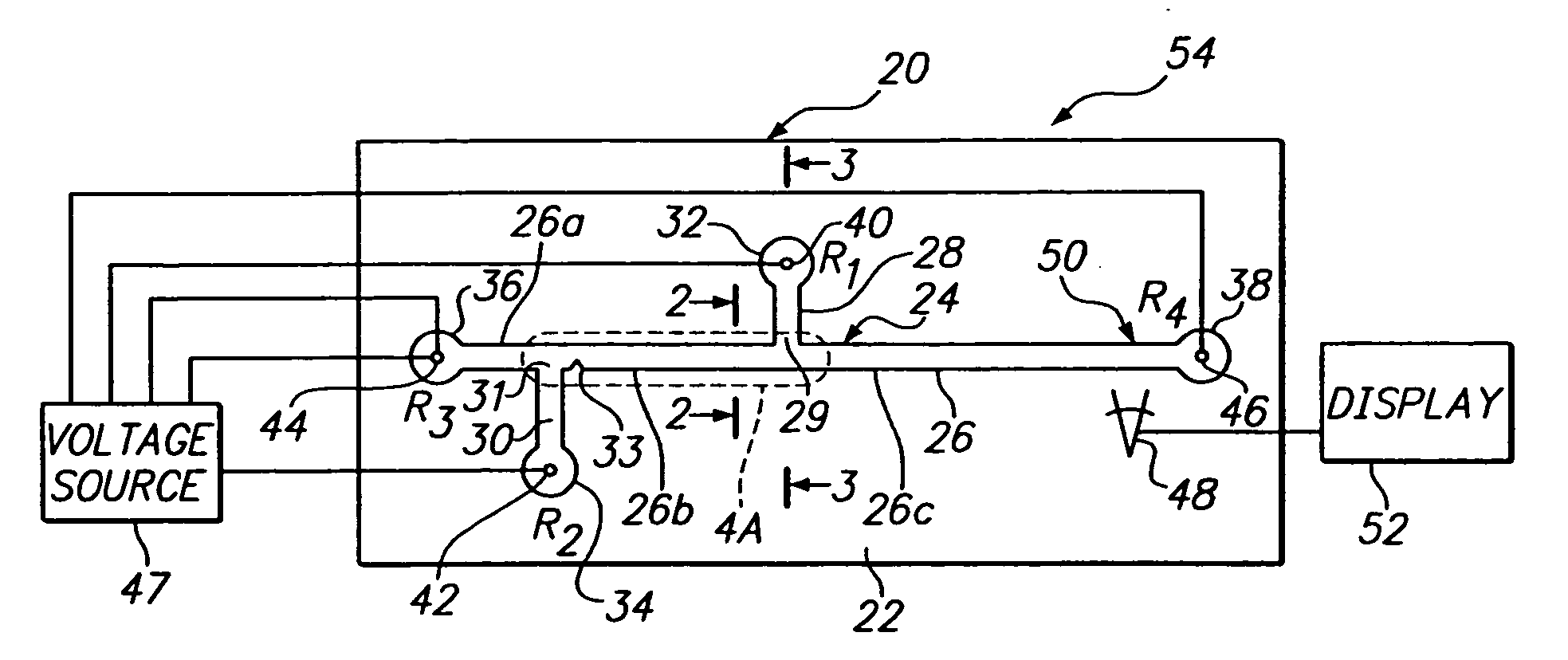
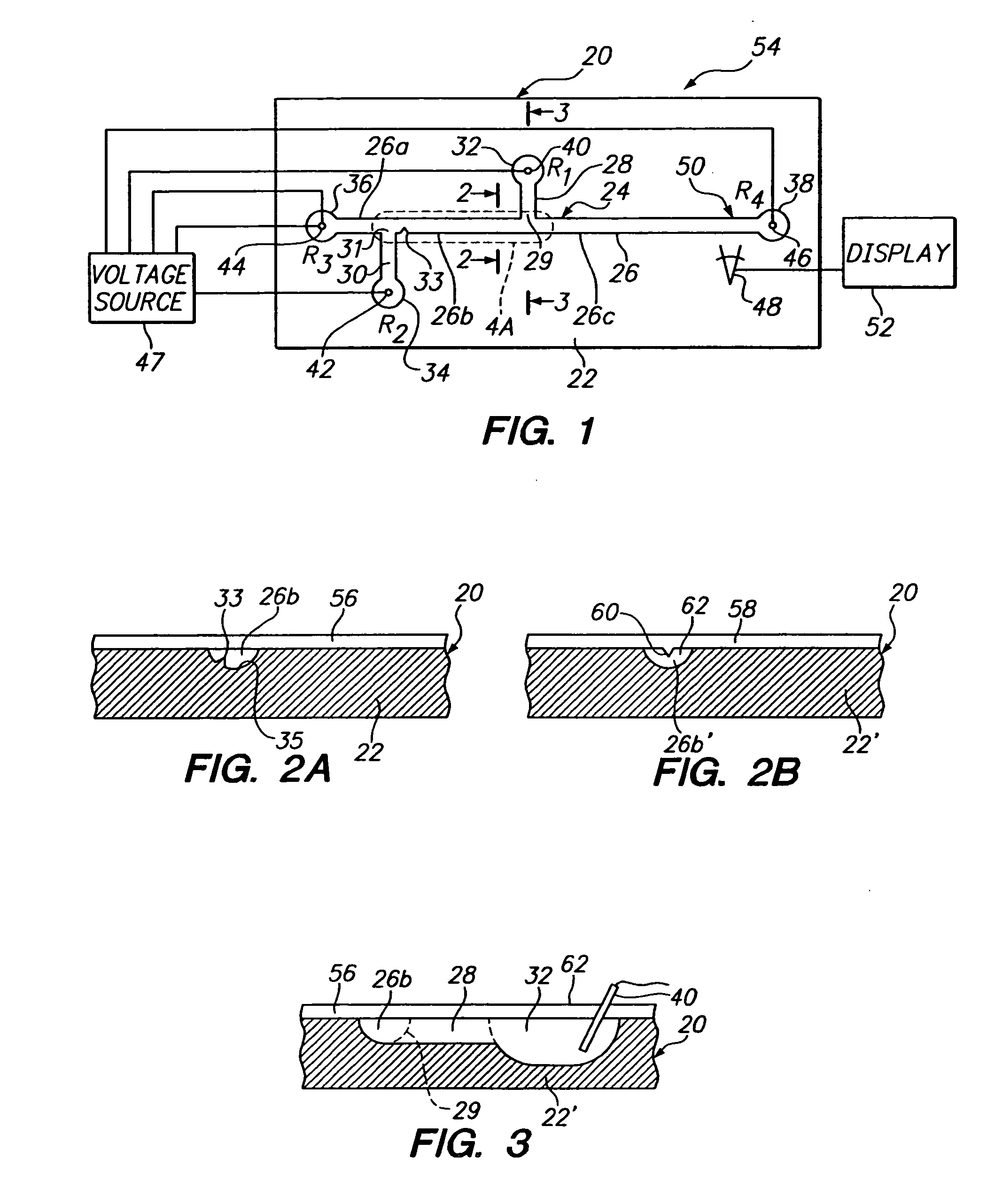
[0029]FIG. 1 illustrates a microfluidics device 20 constructed in accordance with one embodiment of the invention. The device includes a substrate 22, and a microchannel network 24 formed in the substrate. By “microchannel network” is meant one of more microchannels, hereafter referred to as channels, that are preferably between 0.1 μm to 1 mm deep, 0.5 μm to 2 mm wide, and have a cross-sectional area between 0.1 μm2 to about 0.25 mm2. The network in device 20 includes a main channel 26, a pair of side channels 28, 30, and first, second, third, and fourth reservoirs 32, 34, 36, 38, respectively, that communicate with the distal ends of the first and second side channels, and the upstream and downstream ends of the main channel, respectively.

[0030] As seen, side channels 28, 30, intersect the main channel at ports 29, 31, dividing the main channel into three regions: an upstream region 26a extending between reservoir 38 and port 31, a sample-loading region 26b extending between and ...


PUM

PropertyMeasurementUnit
distanceaaaaaaaaaa
distanceaaaaaaaaaa
electric fieldsaaaaaaaaaa

Abstract

A microfluidics device and method for sample loading, concentrating, mixing, and/or reacting is disclosed. The device has a microchannel network that includes a channel segment communicating with first and second reservoirs. A projection formed on a wall portion of the channel segment terminates therein at a point or edge. When a voltage potential is applied across the two reservoirs, the projection functions to create an electric field gradient within the channel segment that causes charged components in the channel segment to concentrate in the region of the projection. The device is useful, for example, in loading a sample of dilute charged components for electrophoretic separation in the device.

Description

FIELD OF THE INVENTION [0001] The field of this invention is microfluidic devices and, in particular, a device designed for improved sample handling operations, such as sample loading, concentrating, mixing and reacting. BACKGROUND OF THE INVENSION [0002] Microtechnology has already and continues to revolutionize numerous aspects of performing operations. As part of this revolution, microfluidics offers small compact devices to perform chemical and physical operations with minute volumes. In this manner, numerous events may be simultaneously performed within a small area using orders of magnitude less reagent and sample than possible with conventional 96-well plates. [0003] One aspect of microfluidics is the use of capillary electrokinetics to move materials in small volumes from one site to another within closed channels created in a solid substrate. Referred to commonly as μTAS or “lab-on-a-chip,” these devices offer numerous advantages for performing chemical operations. The devi...

Claims


Application Information

Patent Timeline
Patent Type & Authority Applications(United States)
IPC IPC(8): C07K1/26G01N27/447
CPCB01L3/502746B01L3/502761B01L2200/0668B01L2300/0816B01L2400/0421B01L2400/086G01N27/44791
Inventor KURNIK, RONALD T.
Owner MONOGRAM BIOSCIENCES
Why Eureka
Try Eureka