Gas detection apparatus and method

a gas detection and gas sensor technology, applied in the direction of electrochemical generators, instruments, material electrochemical variables, etc., can solve the problems of prolonged downtime of gas sensors, water condensation, and anomalous performance of sensing elements

Inactive Publication Date: 2006-06-01
HONDA MOTOR CO LTD
View PDF6 Cites 10 Cited by
  • Summary
  • Abstract
  • Description
  • Claims
  • Application Information

AI Technical Summary

Benefits of technology

[0014] In the above method, the allowing the heater regulator to cause the heater to continue to heat the gas detection chamber may comprise allowing the heater regulator to cause the output of the heater to lower. Optionally, the allowing the heater regulator to cause the heater to continue to heat the gas detection chamber may further comprise allowing the heater regulator to cause the output of the heater to return to a normal operating level when the anomaly detection device detects absence of the previously detected anomaly of the gas sensing element.
[0015] A fuel cell system provided as yet another aspect of the present invention comprises: a fuel cell stack comprised of a plurality of s

Problems solved by technology

On occasion, the water that has condensed from the steam and has thus been contained in the exhaust gas would adhere to a gas sensing element of the gas sensor, which could result in anomalies in performances of the sensing element such as sensitivity for detecting the fuel gas.
However, if the heater is suspended without exception when any anomaly appears, including those determined temporarily

Method used


Image

  • Gas detection apparatus and method
  • Gas detection apparatus and method
  • Gas detection apparatus and method

Examples


Embodiment Construction

)

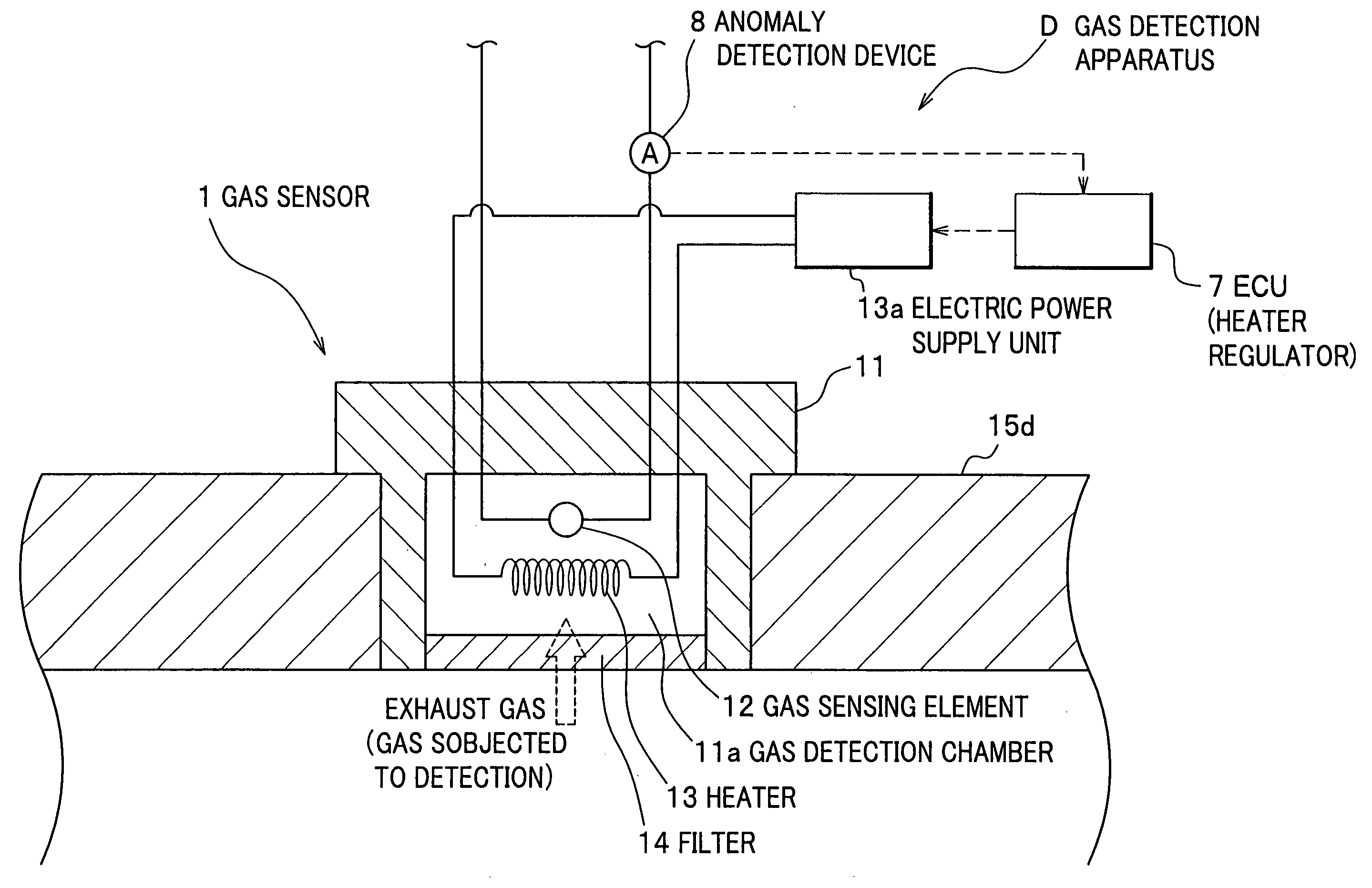
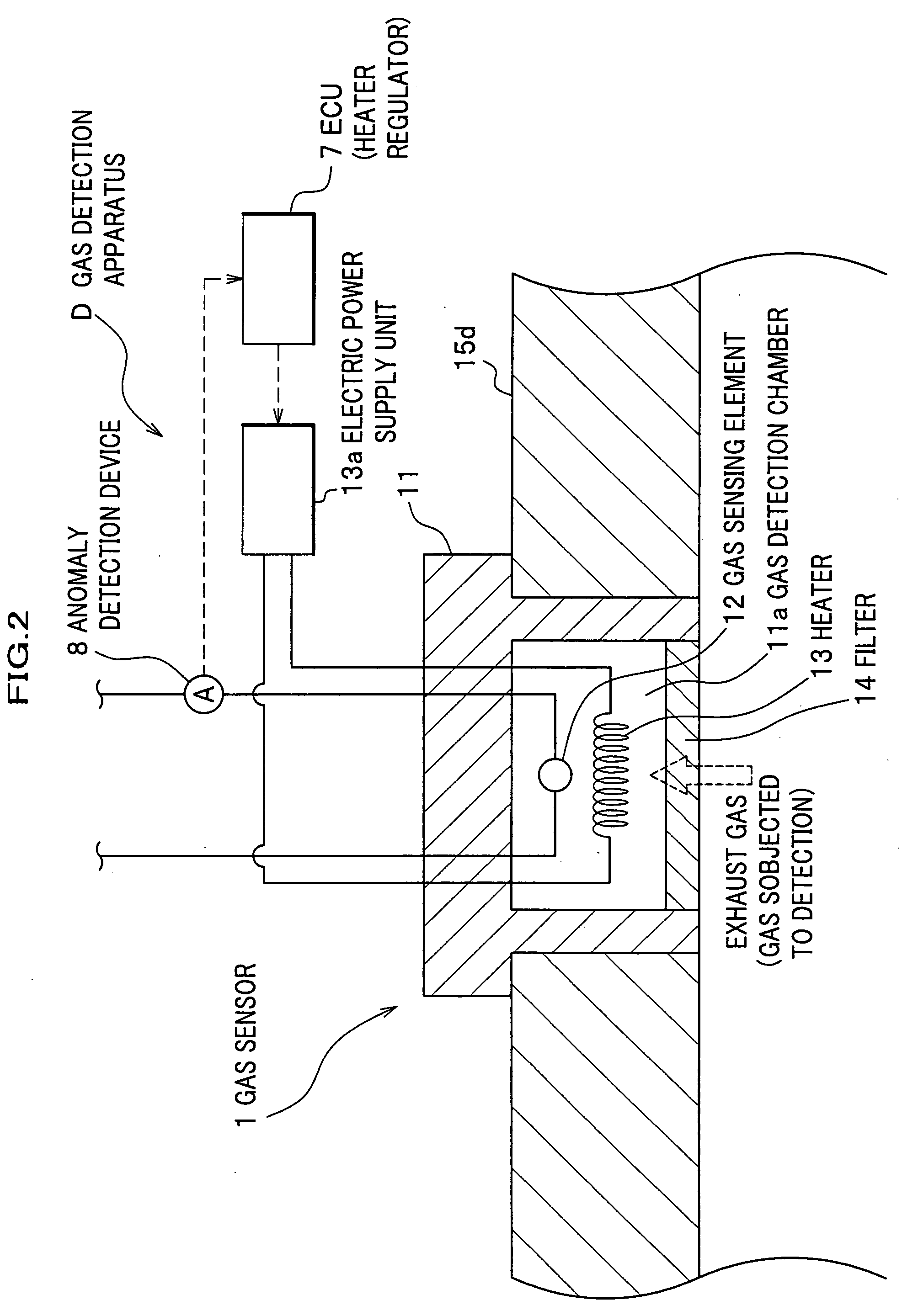
[0023] A detailed description will now be given of a fuel cell system and a gas detection apparatus as one exemplified embodiment of the present invention, and a gas detection method carried out in the fuel cell system.

[Fuel Cell System]

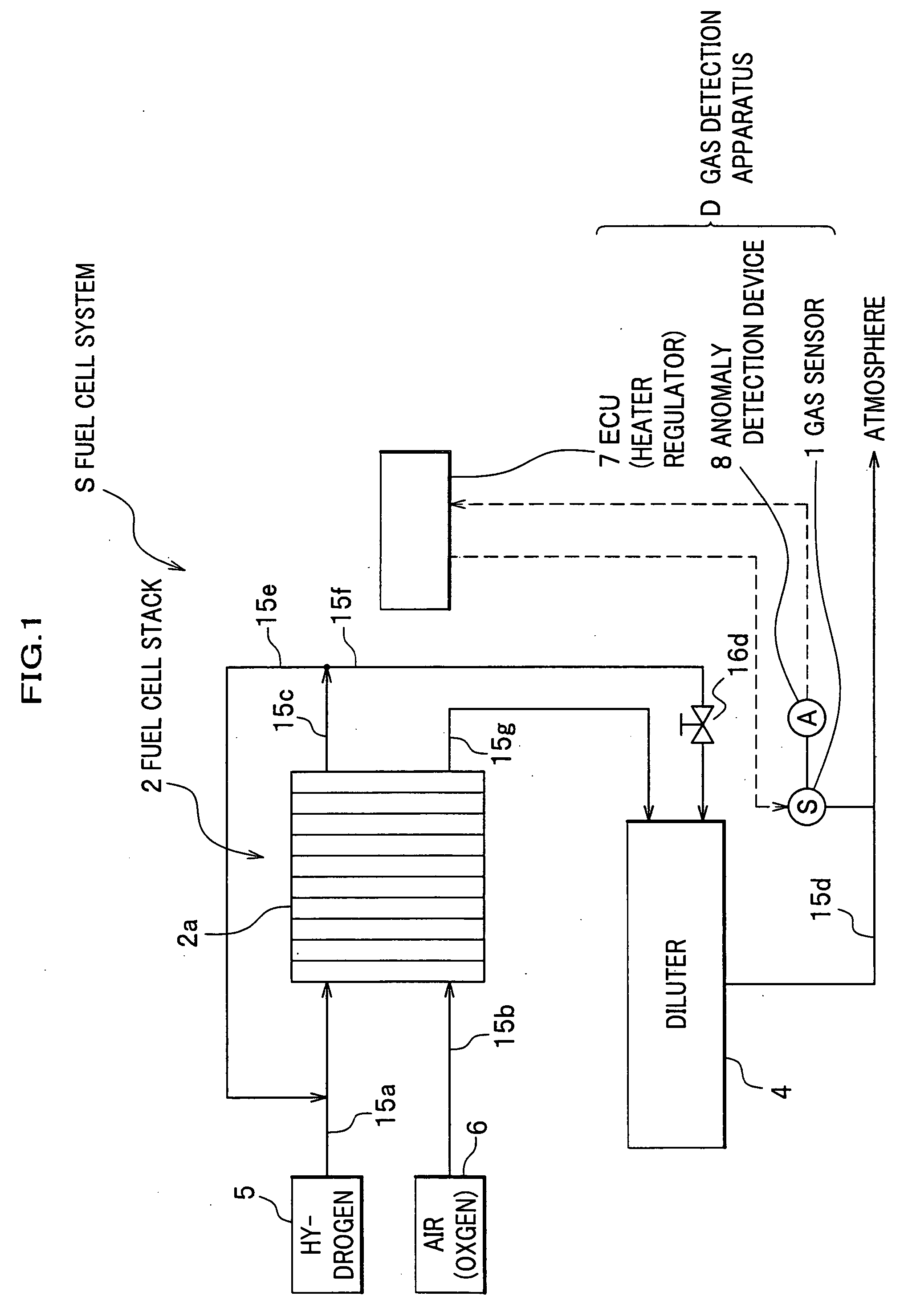
[0024] Referring now to FIG. 1, a fuel cell system S includes a fuel cell stack 2, a diluter 4 and a gas detection apparatus D. The fuel cell system S further includes a high-pressure hydrogen tank 5 from which is supplied a hydrogen gas for fueling the fuel cell stack 2, a compressor 6 for supplying air as an oxidant to the fuel cell stack 2, a radiator (not shown) for cooling a fuel cell stack 2, and other components.

[0025] The fuel cell system 2 is as shown in FIG. 1 comprised of multiple single cells 2a stacked, to generate electricity by electrochemical reaction of the hydrogen gas stored in the high-pressure hydrogen tank 5 and an oxygen gas contained in the air supplied from the compressor 6. An anode side inlet of the fuel cell stack 2 an...


PUM


Abstract

A gas detection chamber in which a gas sensing element is provided to detect a component of a gas allowed into the gas detection chamber is heated by a heater, and an output of the heater is regulated by a heater regulator. The heater regulator is adapted to cause the heater to continue to heat the gas detection chamber (preferably but not necessarily, the output of the heater is caused to lower) when an anomaly detection device detects an anomaly of the gas sensing element.

Description

BACKGROUND OF THE INVENTION [0001] Apparatuses and methods consistent with the present invention relate to detection of a gas. Particularly, the present invention relates to an apparatus and a method for detecting a gas in humid surroundings. [0002] Gas sensors for detecting a fuel gas (hydrogen gas) contained in an exhaust gas of a polymer electrolyte fuel cell are known in the art. For example, a gas sensor disclosed in JP 6-223850 A (see paragraphs 0013 and 0014; FIG. 1) is provided in an exhaust system for discharging a cathode exhaust gas (air) of the fuel cell. This gas sensor is adapted to detect a fuel gas that could accidentally leak from an anode (fuel pole) to a cathode (oxidant pole) through a polymer electrolyte membrane, and used to prevent the fuel gas from being released into the atmosphere. [0003] In general, the exhaust gas of a fuel cell contains a high concentration of water in the form of water vapors or drops derived from water used to humidify the polymer elec...

Claims


Application Information

Patent Timeline
IPC IPC(8): G01N27/26H01M8/00G01F1/64
CPCG01N33/0037G01N33/004G01N33/0044G01N33/005G01N33/0052G01N33/0054H01M8/04007H01M8/04089Y02E60/50Y02A50/20
Inventor SASAKI, TAHASHIOISHI, HIDETOSHISAITO, TAKASHISUZUKI, AKIHIRO
Owner HONDA MOTOR CO LTD
Why Eureka
Try Eureka