
Beam space-charge compensation device and ion implantation system having the same

a compensation device and ion implantation technology, applied in irradiation devices, masers, nuclear engineering, etc., can solve the problems of difficult stable supply of electrons, difficult divergence of ion beams, and difficulty in storing charge (charge-up) onto wafers, so as to improve plasma production and efficiently perform beam space-charge compensation

Inactive Publication Date: 2006-06-01
SENCORP
View PDF3 Cites 13 Cited by
  • Summary
  • Abstract
  • Description
  • Claims
  • Application Information

AI Technical Summary

Benefits of technology

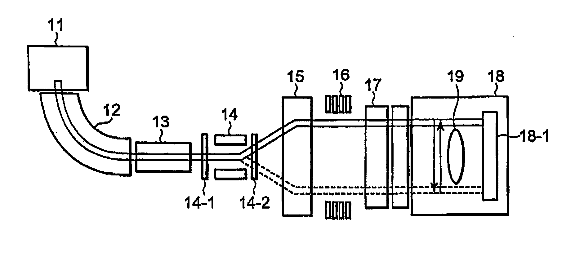
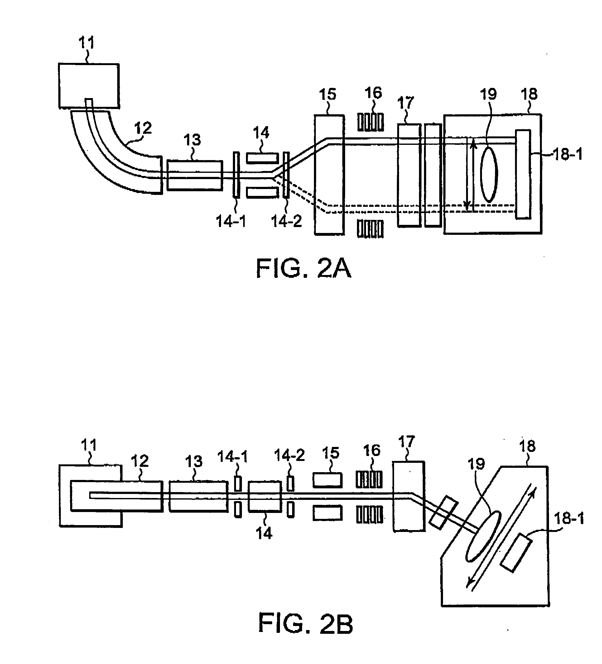
[0017] It is an object of this invention to positively utilize an AEF magnetic field for improvement in production of plasma by a plasma shower, extraction of electrons, and confinement of electrons to thereby efficiently perform beam space-charge compensation without using a particular magnetic field generating device or a particular magnetic field shielding device.
[0018] It is a specific object of this invention to provide a beam space-charge compensation device that can neutralize beam space-charge to suppress divergence of an ion beam, thereby improving the beam transportation compensation efficiency to increase a beam current.

Problems solved by technology

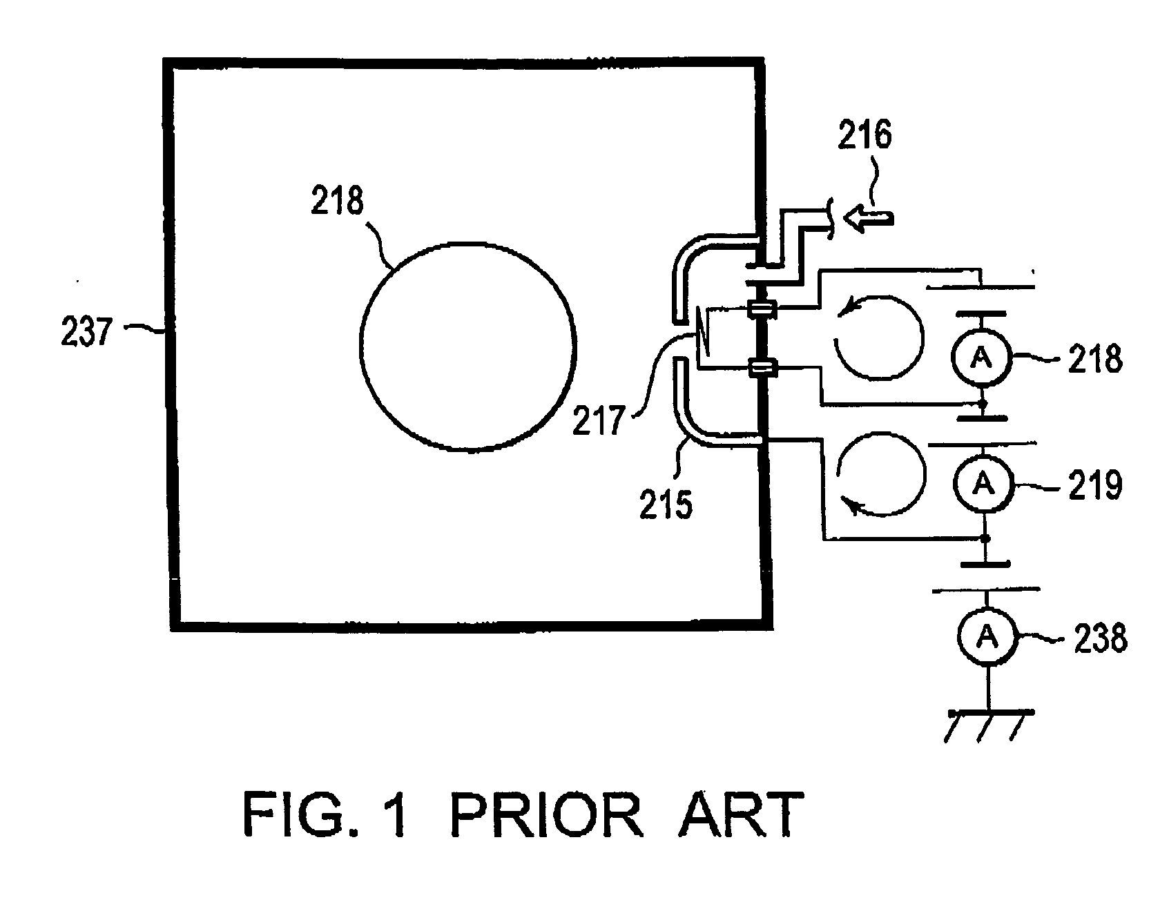
In the ion implantation system, since ions having charges are implanted into a wafer as a processing object, the storage of charge (charge-up) onto the wafer becomes a problem.
In addition, there also arises a problem of divergence of an ion beam due to space charge produced in a beam line.
On the other hand, in an ion implantation system having a deflection mechanism for scanning that carries out beam deflecting for scanning by providing a linear reciprocating motion of an ion beam itself, the relative position between the ion beam and a plasma shower constantly changes and therefore a stable supply of electrons is difficult in view of this, there are proposed various methods for supplying electrons extracted from a plasma shower to an ion beam that is deflected for scanning.
However, in the method of spreading the electrons extracted from the single portion over the deflecting area of the ion beam by the use of the magnetic field, since a leakage magnetic field exists in a beam line, the ion beam is bent so that distribution and implantation angle of the ion beam are adversely affected.
In any event, however, it is not desirable to provide the new mechanism in terms of concern about complexity of the ion implantation system, disturbance of the AEF magnetic field, or the like.

Method used


Image

  • Beam space-charge compensation device and ion implantation system having the same
  • Beam space-charge compensation device and ion implantation system having the same
  • Beam space-charge compensation device and ion implantation system having the same

Examples


first embodiment

[0072] Referring also to FIG. 8 given as an exemplary diagram observing from above an internal structure of the AEF chamber 23, description will be given about a beam space-charge compensation device according to this invention.

[0073] As described before, the AEF chamber 23 includes therein the deflection electrodes 24-1 and 24-2 (illustration of the upper deflection electrode 24-1 being omitted in FIG. 8), the suppression electrodes 31-1 and 31-2, and the ground electrodes 32-1 to 32-4. The deflection electrodes are arranged at least in a pair on the upper and lower sides with respect to the beam advancing direction. The suppression electrodes and the ground electrodes are arranged on the upstream and downstream sides with respect to the beam advancing direction.

[0074] In this embodiment, a plasma shower 10 is further provided in the AEF chamber 23 and one feature of this embodiment resides in that the plasma shower 10 is arranged in the following manner. The plasma shower 10 is d...

second embodiment

[0080] The second change is that an extraction electrode 15 having a hole corresponding to the extraction hole 10-5 is disposed near an outlet side of the extraction hole 10-5 in the plasma shower 10. An extraction voltage is applied across the arc chamber 10-4 and the extraction electrode 15 from an extraction power supply E16. This connection manner is the same with respect to the other plasma shower 10′. Naturally, the first and second changes may be individually applied to the second embodiment shown in FIG. 9. Also in FIG. 10, illustration of the permanent magnets 20 for forming confinement magnetic fields is omitted.

[0081]FIG. 11 shows a beam space-charge compensation device according to a fourth embodiment of this invention. In this fourth embodiment, a plasma shower 10 comprises a first arc chamber 10-1 (same as the arc chamber 10-4 in FIG. 8) and a second arc chamber 10-2. The first arc chamber 10-1 is provided with a filament 10-3, a gas introduction port (not illustrated)...

third embodiment

[0093] Now, description will be given about operation of the third embodiment shown in FIG. 10.

[0094] The second arc voltage is applied from the second arc power supply E14 across the arc chamber 10-4, and the deflection electrodes 24-1 (see FIG. 3) and 24-2 and the ground electrodes 32-2 and 32-3 so that electrons are extracted from the arc chamber 10-4. Herein, the region surrounded by the upper and lower deflection electrodes 24-1 and 24-2 and the upstream and downstream ground electrodes 32-2 and 32-3 in the AEF chamber 23 for beam-guiding serves as a provisional arc chamber so that the electron amount can be increased. In this event, the AEF magnetic field is used as a source magnet. It is preferable not to use the deflection electrodes 24-1 and 24-2, the suppression electrodes 31-1 and 31-2, and the ground electrodes 32-1 to 32-4 for producing AEF and suppression electric fields when the plasma shower is used. This also applies to the embodiments shown in FIGS. 8 and 9.

[0095]...


PUM


Abstract

A beam space-charge compensation device is applied to an angular energy filter provided in an ion beam processing system that performs processing by irradiating onto a wafer with an ion beam. The beam space-charge compensation device comprises a plasma shower provided in a beam-guiding chamber of the angular energy filter. The plasma shower comprises an arc chamber having a filament for generating thermo-electrons for plasma. The arc chamber comprises an extraction hole for extracting the thermo-electrons. The plasma shower is arranged such that the extraction hole is located on lines of magnetic force, perpendicular to an ion beam advancing direction, of the magnetic field and that a center axis of the filament and a center axis of said extraction hole coincide with the lines of magnetic force, perpendicular to the ion beam advancing direction, of the magnetic field.

Description

[0001] This application claims priority to prior application JP 2004-345163, the disclosure of which is incorporated herein by reference, BACKGROUND OF THE INVENTION [0002] This invention relates to an ion implantation system having an angular energy filter that deflects an ion beam by the use of at least one of an electric field and a magnetic field and further relates to a beam space-charge compensation device suitable for application thereto. [0003] An ion implantation system is widely used in the process of manufacturing semiconductor integrated circuits because of its capability of introducing impurities into fine regions of a surface of a processing object with high accuracy. In the ion implantation system, since ions having charges are implanted into a wafer as a processing object, the storage of charge (charge-up) onto the wafer becomes a problem. In addition, there also arises a problem of divergence of an ion beam due to space charge produced in a beam line. [0004] Since t...

Claims


Application Information

Patent Timeline
Patent Type & Authority Applications(United States)
IPC IPC(8): H01J37/08
CPCH01J37/026H01J37/3171H01L21/265
Inventor KAWAGUCHI, HIROSHIYAGITA, TAKANORINISHI, TAKASHIMURAKAMI, JUNICHITSUKIHARA, MITSUKUNIKABASAWA, MITSUAKI
Owner SENCORP
Learn More