Device and method for a functional test of one wind turbine generator plant

a technology of wind turbine generator and test device, which is applied in the direction of simulation control, level control, material dimension control, etc., can solve the problems of inability to test scenarios on real wind turbine generator plants, inability to meet the requirements of constant environmental conditions, and inability to achieve technical feasibility, so as to reduce the time required for system or control development, the effect of rapid and reliable functional testing

Inactive Publication Date: 2006-06-01
NORDEX ENERGY
View PDF0 Cites 42 Cited by
  • Summary
  • Abstract
  • Description
  • Claims
  • Application Information

AI Technical Summary

Benefits of technology

[0008] The inventive method operates with a control unit and at least one simulation unit. The control unit is intended to control the operation of a wind turbine generator plant and reads in actual values from at least one structural part of the wind turbine generator plant and generates control signals for at least one actuator of the wind turbine generator plant. The simulation unit has at least one output and at least one input as well as one or more mathematical models which depict the behaviour of one or more structural parts of the wind turbine generator plant. Mathematical models, in the widest sense, also comprise analytical and physical patterns that produce numerical values as a resultant quantity. Control signals are applied to the input of the simulation unit and the actual values of structural parts of the wind turbine generator plant that are simulated by the models are applied to the output. Both the simulation unit and control units are coupled to each other in such a way that the actual values fro...

Problems solved by technology

Moreover, this way permits to play over scenarios which cannot be tested on a real wind turbine generator plant for reasons of safety or even are not feasible technically.
Wind turbine gene...

Method used


Image

  • Device and method for a functional test of one wind turbine generator plant
  • Device and method for a functional test of one wind turbine generator plant
  • Device and method for a functional test of one wind turbine generator plant

Examples


Embodiment Construction

[0019] While this invention may be embodied in many different forms, there are described in detail herein a specific preferred embodiment of the invention. This description is an exemplification of the principles of the invention and is not intended to limit the invention to the particular embodiment illustrated

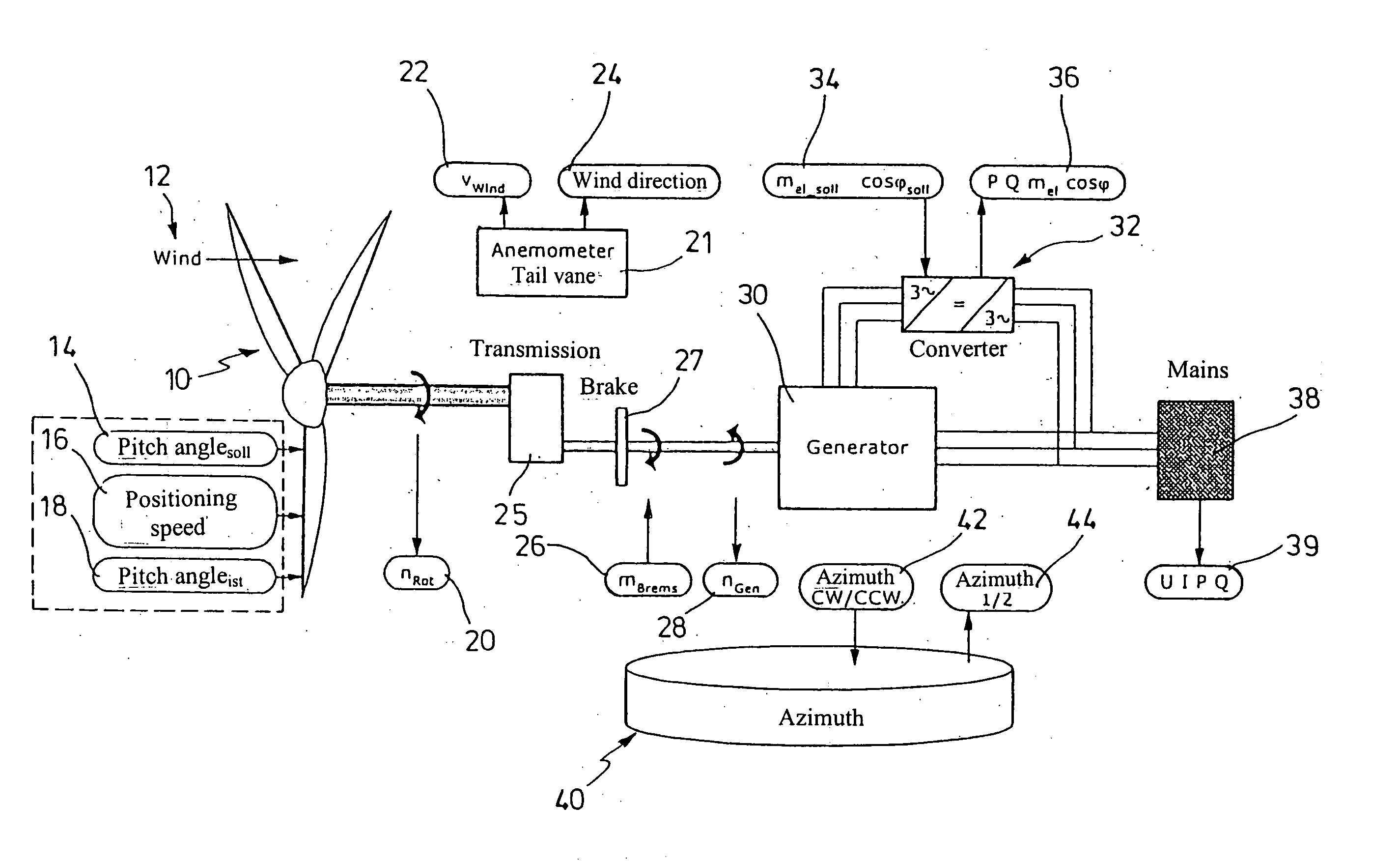
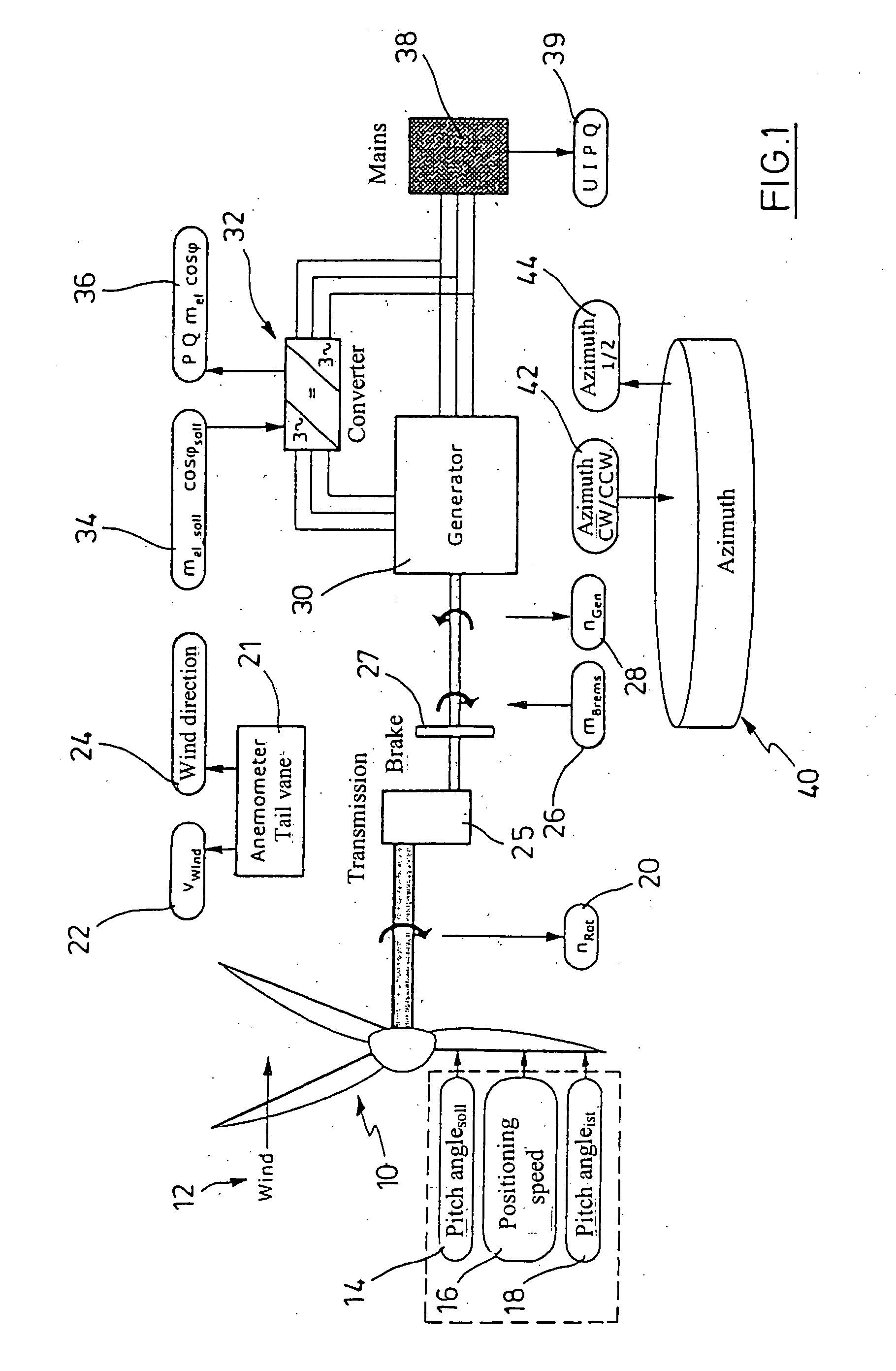
[0020]FIG. 1 schematically shows the structure of the wind turbine generator plant with a rotor 10 to which a flow of air 12 is directed. The rotor has a so-called pitch system by means of which each individual rotor blade is adjustable about its longitudinal axis. This changes the angle of attack to the rotor blade and, thus, the torque acting on the rotor blade. Not only can the pitch angle be predetermined as a setpoint for the pitch system, but the positioning speed 16 can be preset as a control signal in the pitch system as well. The actual pitch angle 18 is the real value for the pitch system. The pitch system offers itself for being depicted, with its actual values an...


PUM


Abstract

A method for a functional test of a wind turbine generator plant which comprises the following procedural steps: a control unit for the wind turbine generator plant reads in actual values from at least one structural part of the wind turbine generator plant and generates control signals for actuators of the wind turbine generator plant, a simulation unit has at least one input and at least one output as well as one or more mathematical models which depict the behaviour of one or more structural parts of the wind turbine generator plant, the control signals are applied to the input of the simulation unit and the modeled actual values of the models on the structural parts are applied to the output of the simulation unit, wherein the actual values of the simulation unit are applied to the input of the control unit and the control signals of the control unit are applied to the input of the simulation unit; the simulation unit models the actual values of the structural parts resulting for the control signals applied, for certain initial conditions.

Description

CROSS-REFERENCE TO RELATED APPLICATIONS [0001] Not applicable. STATEMENT REGARDING FEDERALLY SPONSORED RESEARCH [0002] Not applicable. BACKGROUND OF THE INVENTION [0003] The present invention relates to a device and method for a functional test of one wind turbine generator plant and a wind power system. [0004] Wind turbine generator plants, particularly plants whose power is several megawatts, are provided with a complex control and regulation nowadays. Apart from having the individual assemblies comprised in the wind turbine generator plant which, in turn, themselves constitute complex systems the wind turbine generator plants include a sophisticated control software. The control determines how to operate the wind turbine generator plant, which operating conditions are admissible, which events and states are faulty, and the way the system reacts to such faults. In addition to providing operational safety and smooth operation of the wind turbine generator plant, a centralized funct...

Claims


Application Information

Patent Timeline
IPC IPC(8): F03D9/00H02P9/04F03DF03D1/00F03D7/04
CPCF03D1/003F03D7/045F03D7/047F05B2260/74F05B2260/84F05B2270/708Y02E10/723G05B17/02F03D80/50Y02E10/72
Inventor SCHUBERT, THOMASHESTER, ROBERT
Owner NORDEX ENERGY
Why Eureka
Try Eureka