Fuel cell device assembly and frame

a fuel cell and device technology, applied in the field of fuel cell devices, can solve the problems of cracking of the electrolyte sheet, electrolyte sheet, electrolyte sheet,

Inactive Publication Date: 2006-06-01
CORNING INC
View PDF16 Cites 29 Cited by
  • Summary
  • Abstract
  • Description
  • Claims
  • Application Information

AI Technical Summary

Benefits of technology

[0012] One aspect of the invention is a fuel cell device assembly comprising: (i) an electrolyte sheet; (ii) a plurality of cathodes disposed on one side of the electrolyte sheet; (iii) a plurality of anodes disposed on another side of the electrolyte sheet; and (iv) a frame supporting the electrolyte sheet, the frame having a plurality of channels, such th...

Problems solved by technology

Furthermore, fuel cells endure thermal cycling and large thermal gradients, which induces thermal stresses in the electrolyte sheets.
In addition, a mounted electrolyte sheet will expand at a rate that is different from the thermal expansion rate of its frame, which may cause cracking of the electrolyte sheet.
A defect in an electrolyte sheet may necessitate a replacement of the entire cell or electrolyte device.
The patent discloses that the fuel ce...

Method used


Image

  • Fuel cell device assembly and frame
  • Fuel cell device assembly and frame
  • Fuel cell device assembly and frame

Examples


example 1

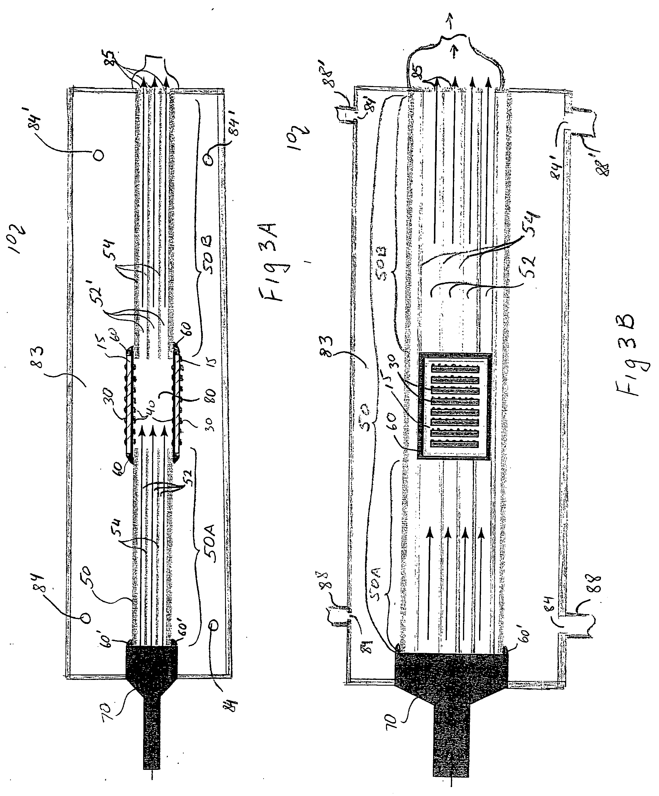
[0035] One exemplary fuel cell device assembly according to the present invention is illustrated schematically in FIGS. 3A and 3B. FIG. 3A is a schematic cross-sectional view of an exemplary fuel cell device assembly 10. FIG. 3B is a schematic illustration of the top (planar) view of fuel cell device assembly illustrated in FIG. 3A. The direction of reactant (e.g., fuel) flow within the fuel cell device assembly is indicated by the arrows.

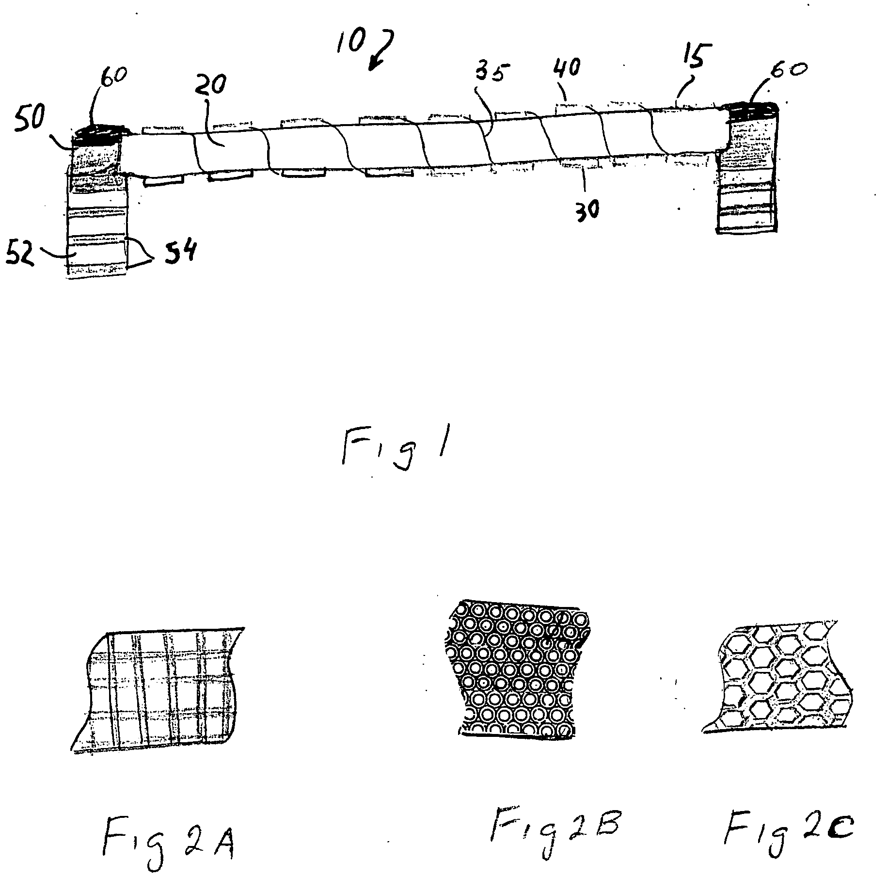
[0036] As shown in these figures, a fuel cell array assembly 10 comprises one fuel cell module 12. The fuel cell module 12 includes the frame 50 that supports two parallel fuel cell arrays 15, oriented such that the two sets of electrodes (e.g., anodes 40) face one another, forming a reactant (e.g., anode) chamber 80 therebetween. The frame 50 is bonded to the fuel cell arrays 15 by sealant 60. Fuel, for use with the fuel cell device assembly 10, is fed towards the frame 50, for example, through a gas distributing end piece 70 which is sealed to t...

example 2

[0038]FIGS. 4A and 4B illustrate another embodiment of the present invention. FIG. 4A is a schematic cross-sectional view of the exemplary fuel cell device assembly providing heat exchange. FIG. 4B is a schematic illustration of the top (planar) view of the fuel cell device assembly illustrated in FIG. 4A.

[0039] In this embodiment the frame 50 is a heat exchanger. The frame 50 supports two parallel fuel cell arrays 15, oriented such that the two sets of anodes 40 face one another, forming anode chambers 80 therebetween. The anode chambers 80 are separated from one another by the heat exchange channel flow portion 80A of the central fuel flow channel(s) 52. According to this embodiment, the frame 50 includes at least one inlet opening 51 coupled to a fuel distribution end piece 70 and at least one exhaust outlet 85′ located on the side of the frame attached to the fuel distribution end piece 70 (i.e. frame section 50A). At least one plug 86 prevents the fuel from exiting the central...

example 3

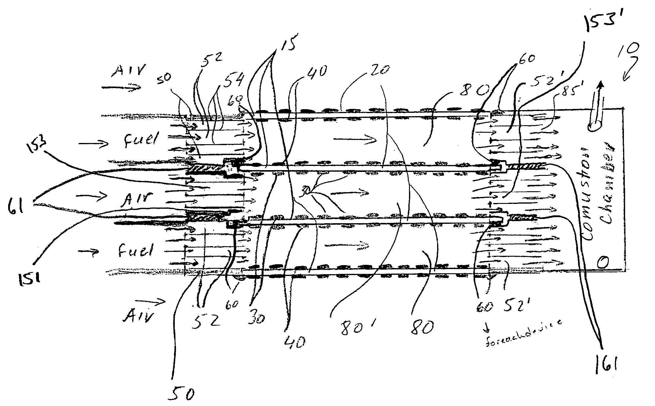
[0041] As shown in FIGS. 5A and 5B, the fuel cell stack may include three or more fuel cell arrays 15 supported by the frame(s) 50, such that (i) anode sides of at least two of the fuel cell arrays 15 face each other, thereby forming an anode chamber 80 and (ii) cathode sides of at least two of the fuel cell arrays 15 also face one another, thereby forming a cathode chamber 80′. As shown in FIG. 5B, frames 50 have a plurality of parallel channels 52 providing (a) fuel gas to the anode chamber 80 and (b) oxygen flow to the cathode chamber 80′. The frames 50 also have a plurality of channels 52′ for the exhaust gases to exit the cathode / anode chambers 80′, 80. As described in the prior examples, the fuel cell arrays 15 are bonded to the frames 50 with a sealant 60. A “packet” type fuel cell stack is formed by utilizing frame(s) 50 and multiple fuel cell arrays to form reactant chambers (packets) therebetween.

[0042] Thus, as shown in FIGS. 5A and 5B, an exemplary fuel cell device asse...


PUM


Abstract

An exemplary fuel cell device assembly includes: (i) an electrolyte sheet; (ii) a plurality of cathodes disposed on one side of the electrolyte sheet; (iii) a plurality of anodes disposed on another side of the electrolyte sheet; and (iv) a frame supporting the electrolyte sheet, the frame having a plurality of channels. Preferably the cross-sectional area of the frame has channel density of at least 20/in2 and channel wall thickness of 50 mils or less.

Description

BACKGROUND OF THE INVENTION [0001] 1. Field of the Invention [0002] The present invention relates generally to fuel cell devices, and particularly to frames for the fuel cell devices. [0003] 2. Technical Background [0004] The use of solid oxide fuel cells has been the subject of considerable amount of research in recent years. The typical components of a solid oxide fuel cell (SOFC) comprise a negatively-charged oxygen-ion conducting electrolyte sandwiched between two electrodes. Electrical current is generated in such cells by oxidation, at the anode, of a fuel material, for example hydrogen, which reacts with oxygen ions conducted through the electrolyte. Oxygen ions are formed by reduction of molecular oxygen at the cathode. [0005] U.S. Patent Publication US2002 / 0102450 and 2001 / 0044041 describe solid electrolyte fuel cells which include an improved electrode-electrolyte structure. This structure comprises a solid electrolyte sheet incorporating a plurality of positive and negati...

Claims


Application Information

Patent Timeline
IPC IPC(8): H01M8/24H01M2/08
CPCH01M8/0273H01M8/0276H01M8/04007H01M8/242Y02E60/50H01M8/02H01M8/24H01M8/0258H01M8/2483
Inventor BADDING, MICHAEL EDWARDBROWN, JACQUELINE LESLIEPOLLARD, SCOTT CHRISTOPHER
Owner CORNING INC
Why Eureka
Try Eureka