
Eye registration system for refractive surgery and associated methods

a registration system and eye technology, applied in the field of eye registration system for refractive surgery, can solve the problems of affecting the accuracy of an alignment, unfavorable patient treatment, and the impression can lose its definition quickly, and achieve the effect of precise registration of the ey

Active Publication Date: 2006-06-01
ALCON INC
View PDF26 Cites 36 Cited by
  • Summary
  • Abstract
  • Description
  • Claims
  • Application Information

AI Technical Summary

Benefits of technology

[0012] Thus an aspect of the present invention provides a system and method for achieving a precise registration of the eye by making sure that an eye feature is positioned in substantially the same location on the superimposed images. As a result, a prescription measurement for reshaping a cornea, for example, will account for the rotation and translation of the eye occurring between measurements made with the patient in a sitting position and laser surgery with the patient in a supine position.
[0013] The features that characterize the invention, both as to organization and method of operation, together with further objects and advantages thereof, will be better understood from the following description used in conjunction with the accompanying drawing. It is to be expressly understood that the drawing is for the purpose of illustration and description and is not intended as a definition of the limits of the invention. These and other objects attained, and advantages offered, by the present invention will become more fully apparent as the description that now follows is read in conjunction with the accompanying drawing.

Problems solved by technology

Techniques known in the art for accommodating this movement have included marking the eye by cauterizing reference points on the eye using a cautery instrument (U.S. Pat. No. 4,476,862) or caustic substance, a very uncomfortable procedure for the patient.
However, the time delay from measurement to surgery often causes the ink to run, affecting the accuracy of an alignment.
However, the impression can lose its definition quickly relative to the time period between the measurement and surgery.

Method used

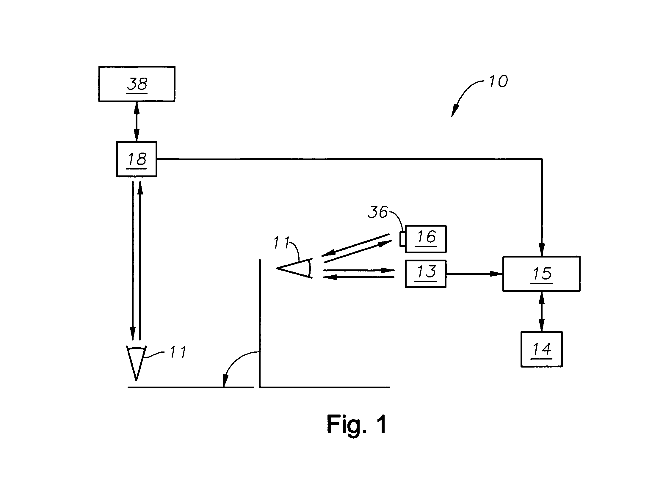
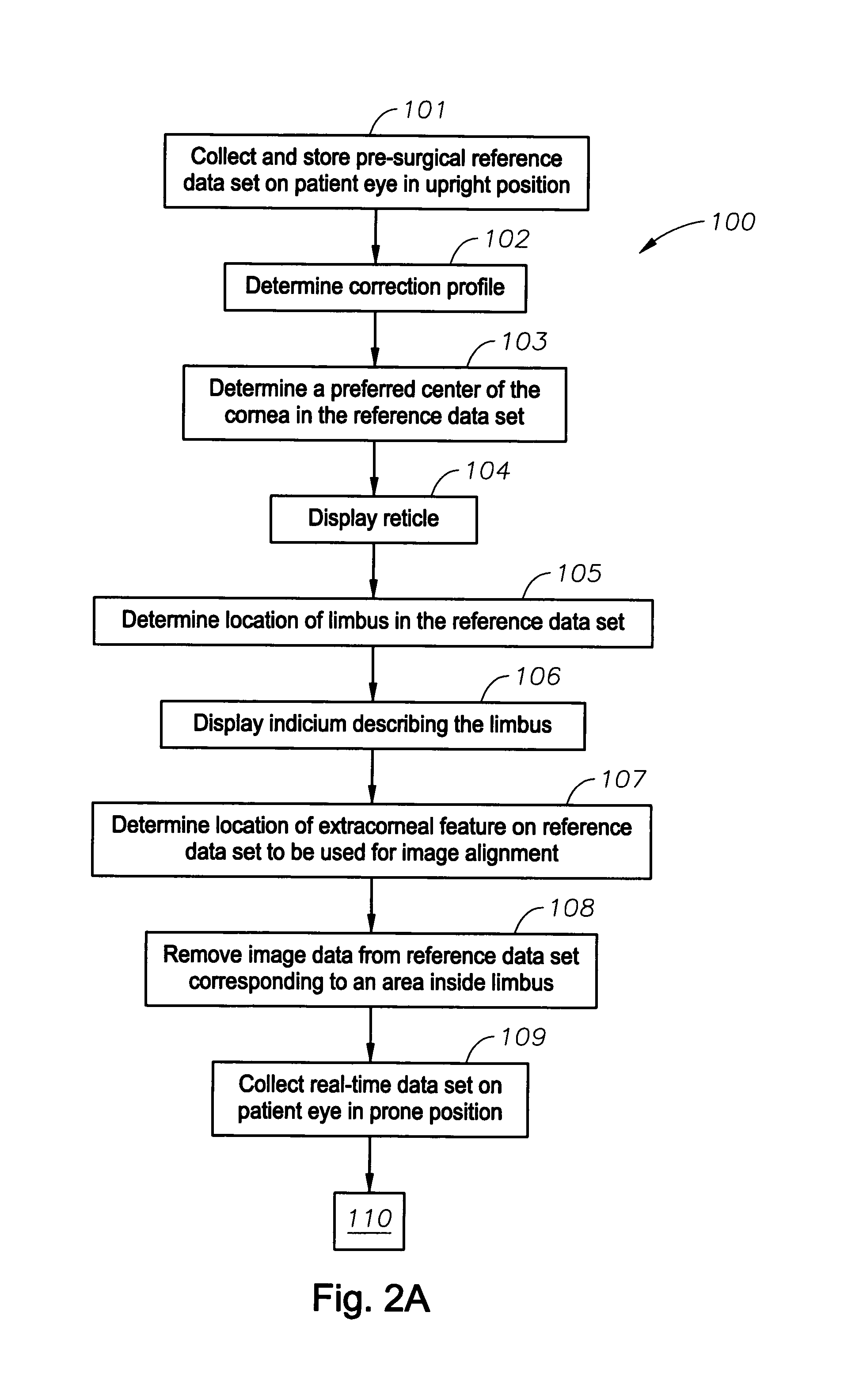

Image

  • Eye registration system for refractive surgery and associated methods
  • Eye registration system for refractive surgery and associated methods
  • Eye registration system for refractive surgery and associated methods

Examples


Embodiment Construction

[0020] A description of the preferred embodiments of the present invention will now be presented with reference to FIGS. 1-6.

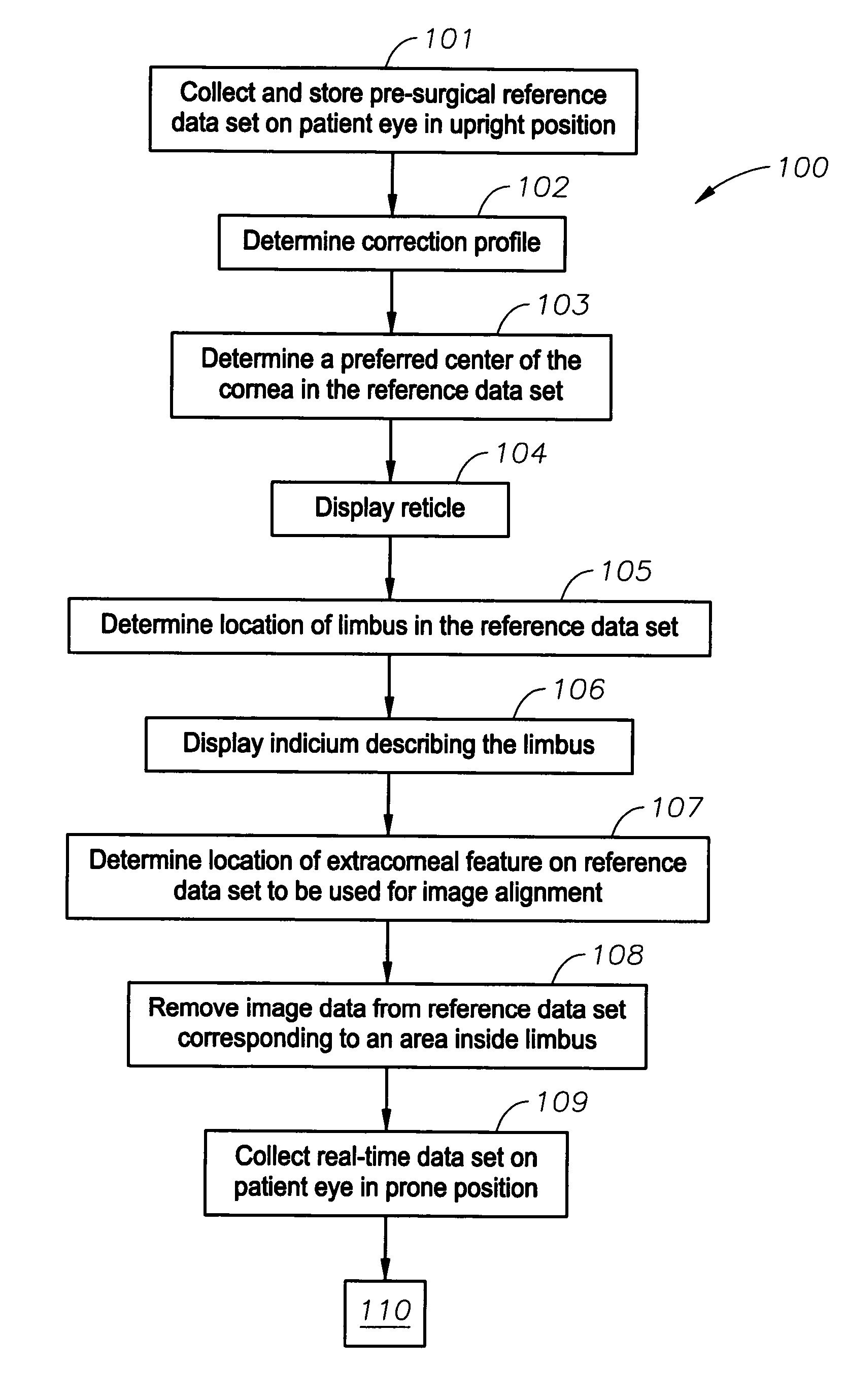
[0021] A schematic diagram of the system 10 of an embodiment of the invention is shown in FIG. 1, data flow of an exemplary embodiment of the method 100 in FIGS. 2A, 2B, and displayed images in FIGS. 3-6. In an exemplary embodiment of the system 10, a patient's eye 11 is imaged in a substantially upright position by capturing a first video image 12 using a camera such as a charge-coupled-device (CCD) camera 13 (block 101). Such an image 12 is illustrated in FIG. 3. The first image, comprising a reference data set, is stored in a database 14 in electronic communication with a processor 15.

[0022] Next an objective measurement is made on the eye 11 to determine a desired correction profile, using a measurement system 16 such as that disclosed in co-pending application Ser. No. 09 / 566,668, although this is not intended as a limitation (block 102).

[0023] Once th...


PUM


Abstract

An orientation method for corrective eye surgery that registers pairs of eye images taken at different times and with the patient in different positions includes retrieving reference digital image data on an eye of the patient, including image data on an extracorneal eye feature. Real-time image data are collected that include image data on the extracorneal eye feature. A combined image is displayed of a superposition of the data sets, and a determination is made as to whether the combined image indicates an adequate registration between them based upon the extracorneal eye feature data in the two data sets. If the registration is not adequate, one of the data sets is manipulated until an adequate registration is achieved. A system is directed to apparatus and software for orienting a corrective program for eye surgery.

Description

TECHNICAL FIELD OF THE INVENTION [0001] The present invention relates to systems and methods for improving objective measurements preceding corrective eye surgery, and, more particularly, to such systems and methods for improving results of corrective laser surgery on the eye. BACKGROUND OF THE INVENTION [0002] Laser-in-situ-keratomileusis (LASIK) is a common type of laser vision correction method. It has proven to be an extremely effective outpatient procedure for a wide range of vision correction prescriptions. The use of an excimer laser allows for a high degree of precision and predictability in shaping the cornea of the eye. Prior to the LASIK procedure, measurements of the eye are made to determine the amount of corneal material to be removed from various locations on the corneal surface so that the excimer laser can be calibrated and guided for providing the corrective prescription previously determined by the measurements. Refractive laser surgery for the correction of astig...

Claims


Application Information

Patent Timeline
IPC IPC(8): A61F9/008A61B18/18
CPCA61B3/113A61B3/152A61F9/008A61F9/00804A61F2009/00846A61F2009/00872
Inventor GRAY, GARY P.CAMPIN, JOHN A.
Owner ALCON INC
Learn More