Optical transmitter

a technology of optical transmitter and optical sleeve, which is applied in the direction of electromagnetic transceivers, electromagnetic lasers, electromagnetic transmission, etc., to achieve the effect of reducing the fluctuation of the emission wavelength of the ld, high loop gain, and large time constan

Active Publication Date: 2006-06-08
SUMITOMO ELECTRIC IND LTD
View PDF5 Cites 2 Cited by
  • Summary
  • Abstract
  • Description
  • Claims
  • Application Information

AI Technical Summary

Benefits of technology

[0010] According to the configuration above, the preset optical transmitter may emit light after the overshoot or undershoot is disappeared by stabling the temperature of the LD, which suppresses the fluctuation in the emission wavelength of the LD just after the transmitter is powered on. The conventional temperature control for the laser diode using a feedback loop, due to the...

Problems solved by technology

The conventional temperature control for the laser diode using a feedback loop, due to the high loop gain and a large time constant for the elemen...

Method used


Image

  • Optical transmitter
  • Optical transmitter
  • Optical transmitter

Examples


first embodiment

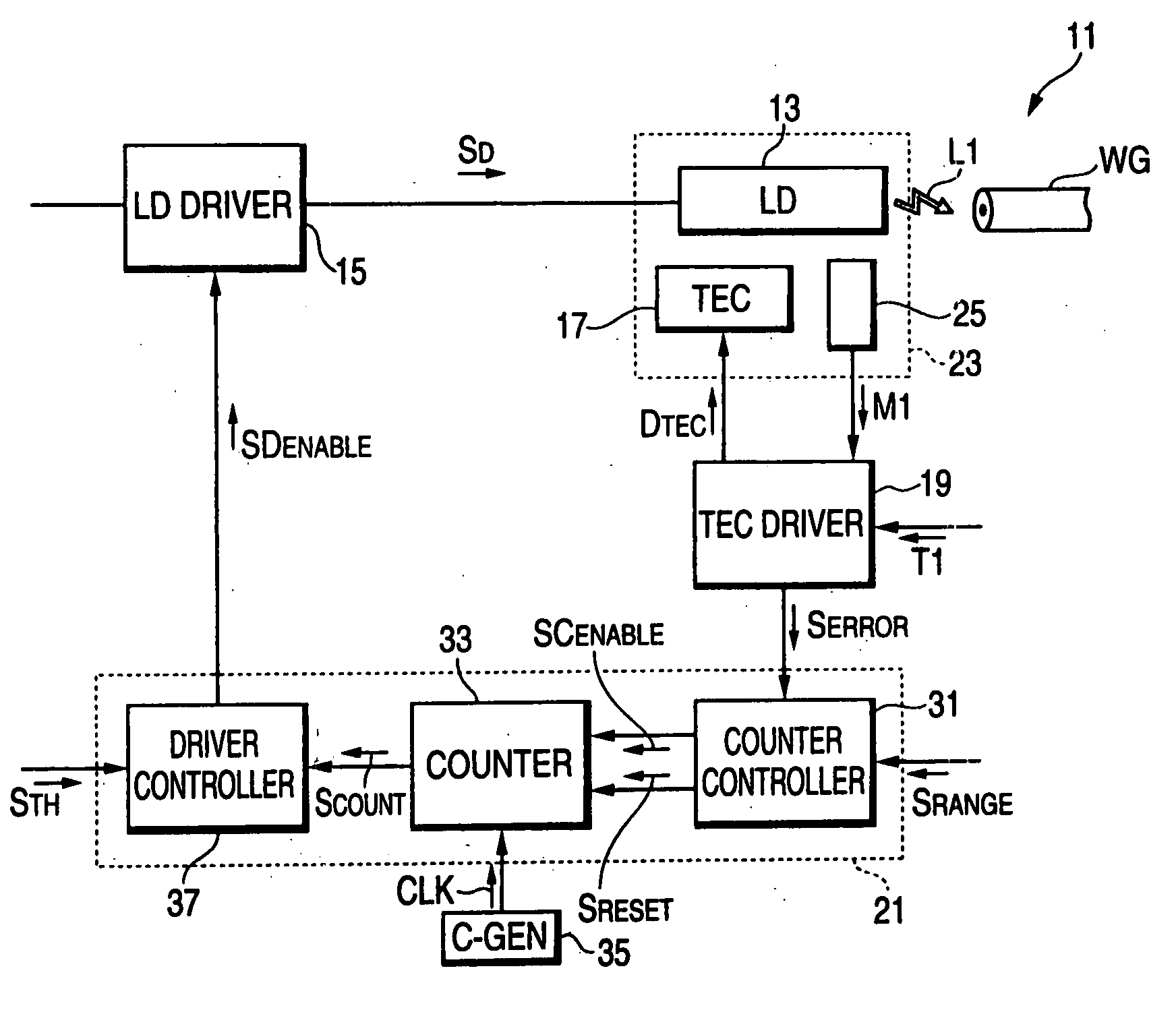
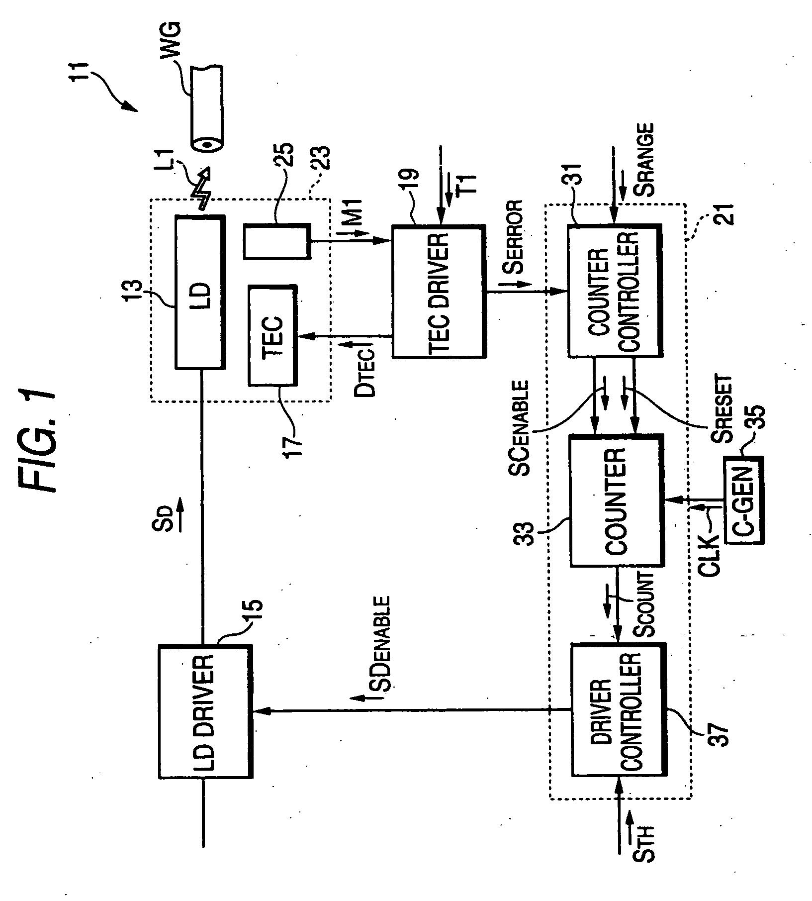
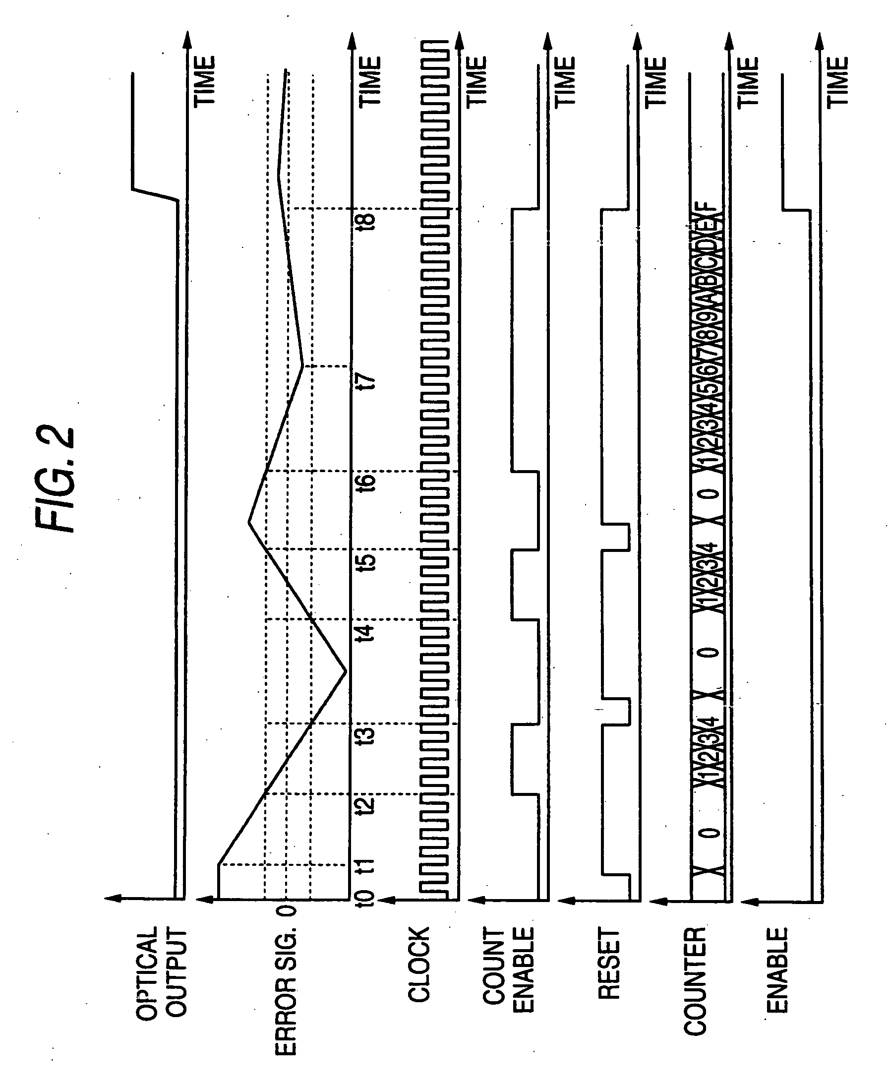
[0025]FIG. 1 is a block diagram of an optical transmitter according to the first embodiment of the invention. The optical transmitter 11 comprises a laser diode (hereinafter denoted as LD) 13, an LD-Driver 15, a thermoelectric controller (TEC) 17, a TEC driver 19, and a master controller 21. The LD may be a type of Fabry-Perot LD, distributed feedback (DFB) LD, or vertical cavity surface emitting laser (VCSEL). The TEC 17 controls a temperature of the LD 13, and may use a Peltier element device. The LD-Driver 15 outputs a driving signal SD to the LD 13, and the LD 13, responding to this driving signal SD, emits signal light L1 that enters the optical fiber WG optically coupled with the LD 13.

[0026] The TEC driver 19 receives the temperature monitoring signal M1 and temperature setting signal T1 corresponding to the target temperature T1 of the LD 13. The controller 19 outputs, responding thus received temperature monitoring signal M1 and the temperature setting signal T1, the TEC c...

second embodiment

[0040]FIG. 6 is another block diagram of the optical transmitter according to the present invention. This transmitter 41 provides a master controller 51 different to that provided in the first embodiment shown in FIG. 1.

[0041] The master controller 51 comprises a range monitor 53, a slope monitor and a driver controller 57. The range monitor 53, by receiving a first range signal SRANGE1 and the error signal SERROR from the TEC driver 19, outputs a first signal S1 to the driver controller 57 when the error signal SERROR is within the first convergent range SRANGE1. The slope monitor 55, by receiving a second range signal SRANGE2 and the error signal SERROR, determines the slope of the error signal SERROR against the time and outputs a second signal S2 to the driver controller 57 when the slope of the error signal SERROR is within the second range signal SRANGE2. The driver controller 57, by receiving the first signal S1 from the range monitor 53 and the second signal S2 from the slo...


PUM


Abstract

The present invention provides an optical transmitter that prevent the overshoot and undershoot appeared in the emission wavelength caused by the fluctuation of the temperature of the laser diode installed therein. The optical transmitter includes a TEC driver, and a master controller. The TEC driver, by comparing the monitored temperature with the target temperature, outputs the error signal to the master controller, which enables the LD-Driver only when the error signal continuously stays within a convergent range by a preset period.

Description

BACKGROUND OF THE INVENTION [0001] 1. Field of the Invention [0002] The present invention relates to an optical transmitter, in particular, the invention relates to the optical transmitter with a function to prevent the overshooting and the undershooting in an optical output at the beginning of the feedback operation. [0003] 2. Related Prior Art [0004] The United States patent, U.S. Pat. No. 5,978,395, has disclosed an optical transmitter for the wavelength division multiplex (WDM) optical communication. The driver circuit disclosed in this patent provides a temperature control circuit to set the temperature of the laser diode (hereinafter denoted as LD) to a value where the LD emits light with a prescribed wavelength. This feedback circuit for stabilizing the temperature of the LD utilizes an error signal, difference between the practical temperature monitored by a temperature sensor and a target temperature for the LD to emit light with the prescribed wavelength. The LD-driver in ...

Claims


Application Information

Patent Timeline
IPC IPC(8): H01S3/10H04B10/07H04B10/293H04B10/40H04B10/50H04B10/524H04B10/54H04B10/564H04B10/572H04B10/60
CPCH01S5/02284H01S5/02415H01S5/042H01S5/0612H01S5/06825H01S5/06837H01S5/02251
Inventor KAWAGISHI, TORUICHINO, MORIYASU
Owner SUMITOMO ELECTRIC IND LTD
Why Eureka
Try Eureka