
System and method for optical heterodyne detection of an optical signal including optical pre-selection that is adjusted to accurately track a local oscillator signal

a detection system and optical signal technology, applied in the field of optical measurement and measuring systems, can solve the problems of limiting the resolution that can be obtained, the signal-to-noise ratio of the heterodyne signal is often degraded, and the amplification also increases the intensity noise of the input signal

Inactive Publication Date: 2006-06-08
TUCKER RODNEY S +2
View PDF10 Cites 24 Cited by
  • Summary
  • Abstract
  • Description
  • Claims
  • Application Information

AI Technical Summary

Benefits of technology

The invention is about an optical heterodyne detection system and method that can accurately track the frequency of a swept local oscillator signal. This is achieved by dithering the passband of the optical pre-selector and adjusting it in response to a measure of the frequency of the swept local oscillator signal and a measure of a portion of the swept local oscillator signal after it has interacted with the optical pre-selector. The system has a high signal-to-noise ratio over a wide range of optical wavelengths and can be used for optical spectrum analysis, optical network analysis, or optical component analysis.

Problems solved by technology

For example, grating-based OSAs and autocorrelation-based OSAs encounter mechanical constraints, such as constraints on beam size and the scanning of optical path lengths, which limit the resolution that can be obtained.
However, the signal-to-noise ratio of the heterodyne signal is often degraded by noise that is contributed from the direct detection signals, especially in the DWDM case where the input signal includes closely spaced carrier wavelengths.
Although amplifying the input signal increases the amplitude of the heterodyne signal, the amplification also increases the intensity noise of the input signal and may not improve the signal-to-noise ratio of the heterodyne signal.

Method used


Image

  • System and method for optical heterodyne detection of an optical signal including optical pre-selection that is adjusted to accurately track a local oscillator signal
  • System and method for optical heterodyne detection of an optical signal including optical pre-selection that is adjusted to accurately track a local oscillator signal
  • System and method for optical heterodyne detection of an optical signal including optical pre-selection that is adjusted to accurately track a local oscillator signal

Examples


Embodiment Construction

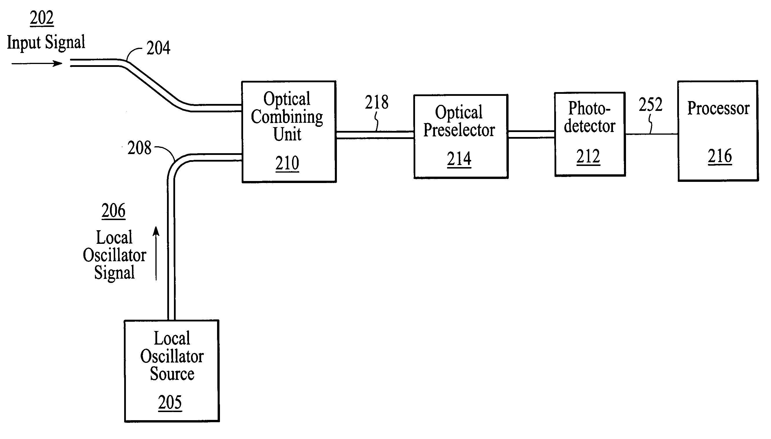
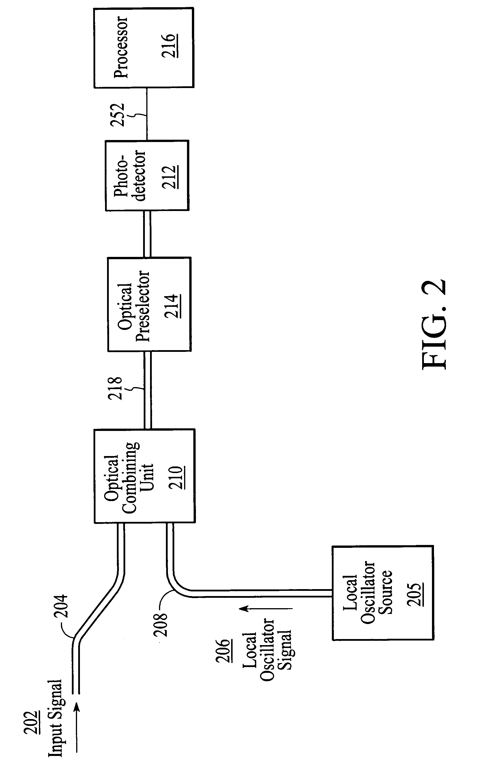
[0035] A method and system for ensuring that the tunable optical pre-selector accurately tracks the frequency of the swept local oscillator signal involves adjusting the optical pre-selector in response to a measure of the frequency of the swept local oscillator signal and in response to a measure of a portion of the swept local oscillator signal after the portion of the swept local oscillator signal has optically interacted with the optical pre-selector. Additionally, the optical pre-selector is dithered such that a dither is imparted on the portion of the swept local oscillator signal that interacts with the optical pre-selector. Dithering the optical pre-selector enables the generation of an error signal that represents the offset between the center frequency of the optical pre-selector and the frequency of the swept local oscillator signal. The error signal is used to drive the center frequency of the optical pre-selector to the frequency of the swept local oscillator signal. De...


PUM

PropertyMeasurementUnit
modulation frequencyaaaaaaaaaa
drive voltageaaaaaaaaaa

Abstract

An optical heterodyne detection system includes a tunable optical pre-selector that is adjusted to track the frequency of a swept local oscillator signal. The tunable optical pre-selector is adjusted in response to a measure of the frequency of the swept local oscillator signal and in response to a measure of a portion of the swept local oscillator signal after the portion of the swept local oscillator signal optically interacts with the pre-selector. Additionally, the pre-selector is dithered such that a dither is imparted on the portion of the swept local oscillator signal that interacts with the optical pre-selector.

Description

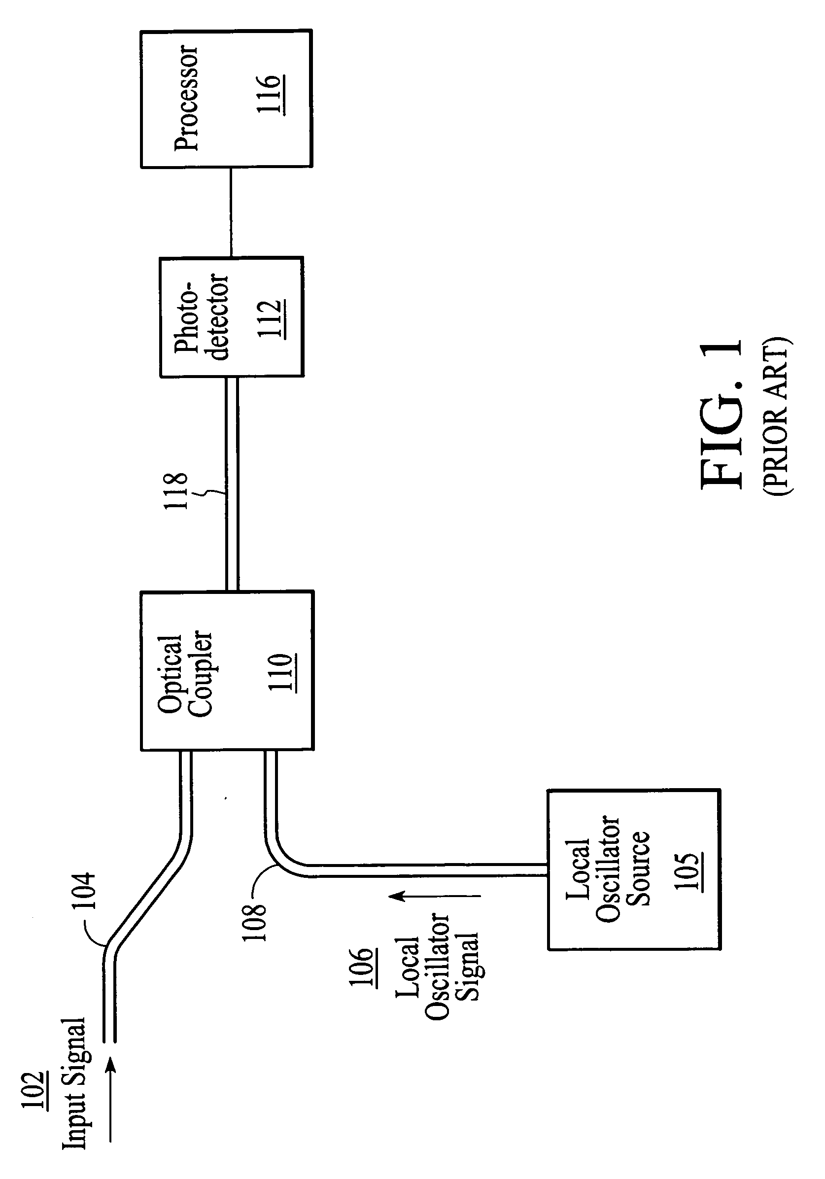
CROSS-REFERENCE TO RELATED APPLICATIONS [0001] This application is a Divisional of co-pending application Ser. No. 09 / 684,371, filed Oct. 5, 2000.FIELD OF THE INVENTION [0002] The invention relates generally to the field of optical measurements and measuring systems, and more particularly to a system and method for optical heterodyne detection of an optical signal. BACKGROUND OF THE INVENTION [0003] Dense wavelength division multiplexing (DWDM) requires optical spectrum analyzers (OSAs) that have higher spectral resolution than is typically available with current OSAs. For example, grating-based OSAs and autocorrelation-based OSAs encounter mechanical constraints, such as constraints on beam size and the scanning of optical path lengths, which limit the resolution that can be obtained. [0004] As an alternative to grating-based and autocorrelation-based OSAs, optical heterodyne detection systems can be utilized to monitor DWDM systems. FIG. 1 is a depiction of a prior art optical het...

Claims


Application Information

Patent Timeline
Patent Type & Authority Applications(United States)
IPC IPC(8): H04B10/06G01J9/00G02F2/00H04B10/04H04B10/142H04B10/148H04B10/152H04J14/00H04J14/02
CPCH04B10/60H04B10/64
Inventor TUCKER, RODNEY S.BANEY, DOUGLAS M.SORIN, WAYNE V.
Owner TUCKER RODNEY S
Learn More