
Toroidal type continuously variable transmission

Inactive Publication Date: 2006-06-08
NSK LTD
View PDF6 Cites 7 Cited by
  • Summary
  • Abstract
  • Description
  • Claims
  • Application Information

AI Technical Summary

Benefits of technology

[0024] The present invention is made in the light of the above-mentioned conventional circumstances. That is, it is one of objects of the invention to provide a toroidal type continuously variable transmission which not only can apply the optimum pressing force in accordance with transmission gear ratios but also can obtain a desired transmission gear ratio with a lower pressing force than the conventional transmission to thereby reduce the occurrence of torque shift.
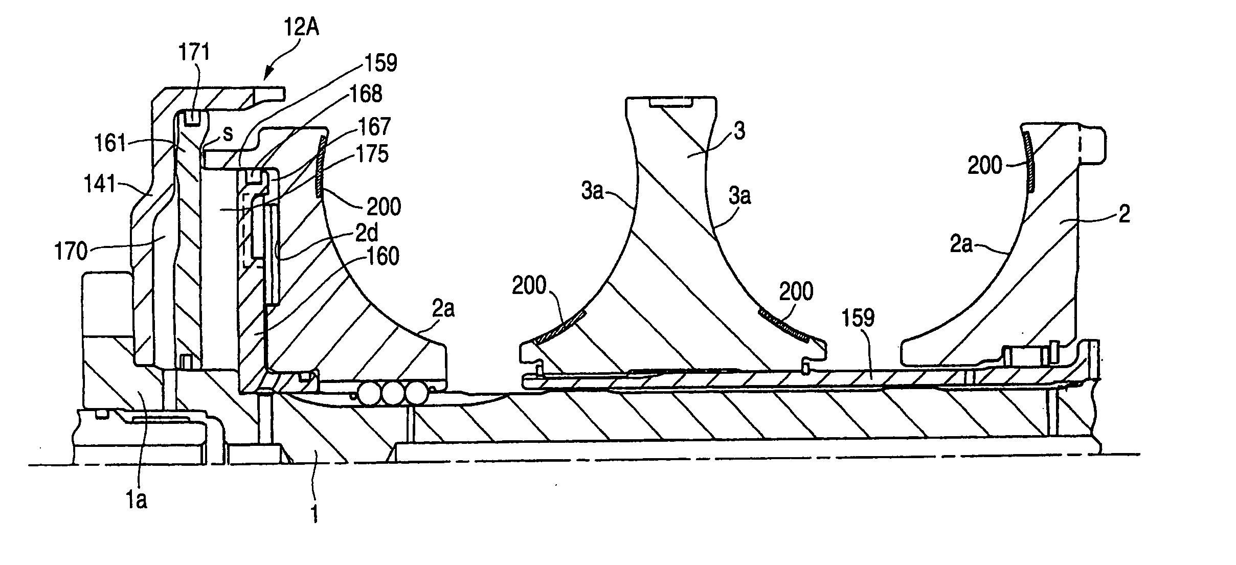
[0044] In a toroidal type continuously variable transmission according to the invention, due to use of a pressing device of a hydraulic type, the optimum pressing force can be applied in accordance with transmission gear ratios; and, at the same time, because there are formed fine grooves in the inner peripheral surface areas of the input and output side disks where the disks are contacted with the power rollers at least at the switching areas of the speed modes or in the neighborhood of such peripheral surfaces areas, the design traction coefficient can be increased, thereby being able to reduce the pressing force. Thanks to this, by reducing the pressing force in the periphery of the switching areas of the speed modes, the torque shift can be reduced, or it is possible to secure an allowance for the gross slip at the switching areas of the speed modes.
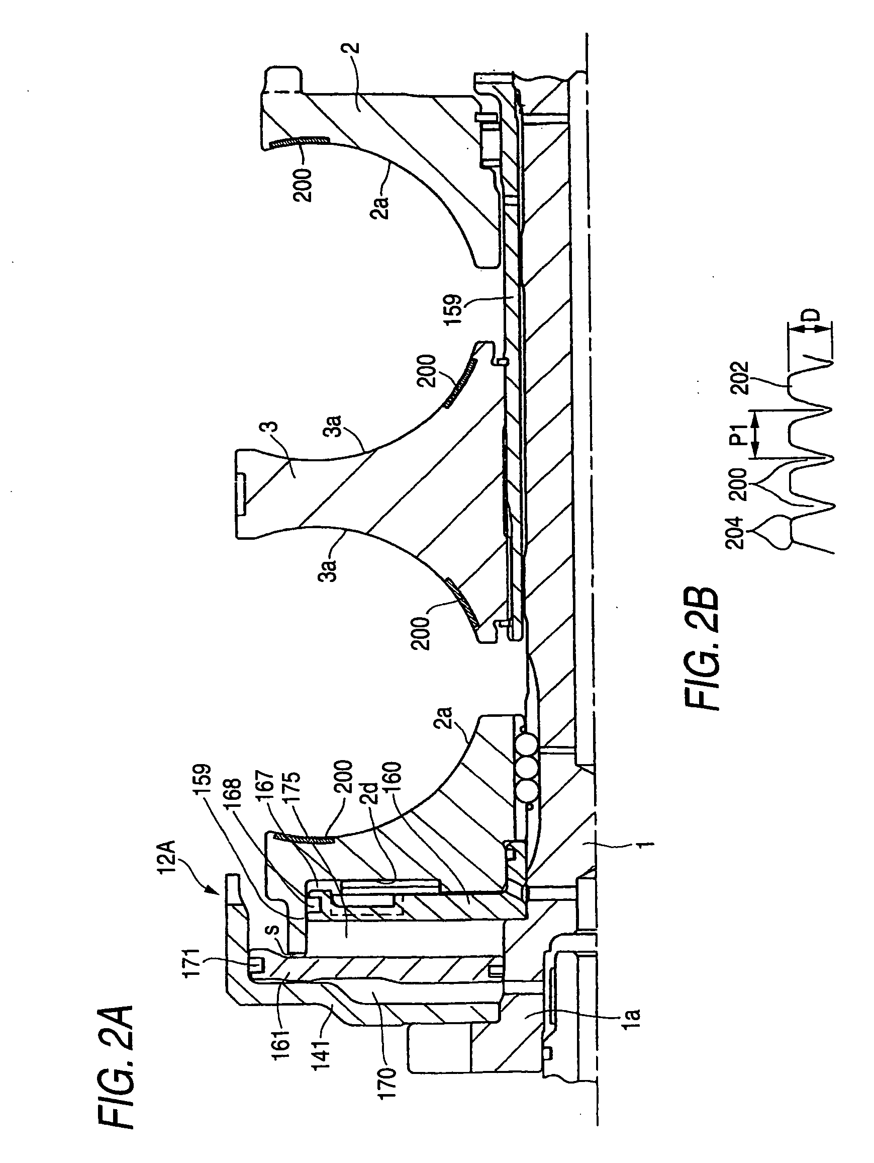
[0045] By the way, the above-mentioned fine groove may preferably have a depth of about 1-10 μm and a pitch of about 100-300 μm. Also, if the roughness of the fine groove is large, there is a possibility that the rolling life thereof can be shortened. Therefore, preferably, the fine groove may not be formed on the entire traction surface but they may be formed only at the switching areas of the speed modes. This arrangement is advantageous in working as well. That is, in the case of the fine grooves, it is necessary to round the head portions thereof or the corner portions thereof, which requires an extra finishing step for execution of such rounding operations. However, when the fine grooves are formed only at the speed mode switching areas to thereby narrow the finishing range, the working cost of the fine grooves can be reduced.
[0046] In a toroidal type continuously variable transmission according to the invention, due to use of a pressing device of a hydraulic pressure type, the optimum pressing force can be applied in accordance with transmission gear ratios; and, at the same time, because there are formed fine grooves at least in the radially inner part of the inner peripheral surface of the above-mentioned input side disk and in the radially outer part of the inner peripheral surface of the above-mentioned output side disk, that is, in the contact areas between the input and output side disks and their respective power rollers which correspond to the low speed (speed reducing) time, the design traction coefficient can be increased. Thanks to this, not only the pressing force can be reduced but also the durability of the respective parts (for example, disks, power rollers, trunnions, shafts and the like) can be enhanced, whereby the size of the transmission can be reduced.
[0047] By the way, each of the above-mentioned fine grooves preferably has a depth of about 1-10 μm and a pitch of 100-300 μm. Also, when the roughness of the fine groove is large, there is a possibility that the rolling life can be shortened. Therefore, preferably, the fine grooves may not be formed in the entire areas of the traction surface but may be formed only on the low speed side which is low in the frequency of use and provides a high load. This arrangement is advantageous also in working. That is, in forming the fine grooves, the head portions or corner portions thereof must be rounded, which requires a separate finishing step of rounding these portions. If the fine grooves are formed only on the low speed side to thereby narrow the finishing range, the working cost of the fine grooves can be reduced.

Problems solved by technology

In the case where only the pressing device 12 of a loading cam type, there is generated a thrust force (the pressing force of the input side disk) in proportion only to the input torque; and, therefore, depending on the transmission gear ratios, there is a fear that an excessive pressing force can act on the contact portions between the disks and rollers to thereby reduce the transmission efficiency and durability of the composing members.
This torque shift is caused by a difference in transformation between the composing members due to variations in the pressing force or by the rickety motion and worsened rigidity of the trunnions and power rollers due to variations in the traction force.
When such torque shift is produced, in the mode switching time, a shock is given to the transmission and thus an automobile carrying the transmission on board, which reduces the riding feeling of the automobile.
Also, when sudden torque shift occurs, there is a possibility that inconveniences such as a gross slip can be produced.
However, in the low speed time, due to the contact radius and transmission torque between the input side disk and power roller, there is required a high pressing force (in a toroidal type continuously variable transmission, the contact radius between the disk and power roller varies in accordance with transmission gear ratios and thus the necessary pressing force varies).
Therefore, the surface pressure of the contact portion between the disk and power roller (in the case of a half toroidal type continuously variable transmission, the surface pressure of the power roller 1011 as well) becomes high, which has ill effects on the durability of the composing parts.
Also, when the durability of the composing parts is raised, they become large in size.

Method used


Image

  • Toroidal type continuously variable transmission
  • Toroidal type continuously variable transmission
  • Toroidal type continuously variable transmission

Examples


Embodiment Construction

[0057] Now, description will be given below of an embodiment according to the invention with reference to the accompanying drawings. Here, the characteristic aspect of the invention consists in a disk surface structure for reducing a pressing force applied by a pressing device and the other remaining structures and operations thereof are similar to the before-mentioned conventional structures and operations. Therefore, in the following description of this specification, only the characteristic portions of the invention will be described and other remaining portions will be explained only briefly with the same reference characters as shown in FIGS. 3 and 4 given.

[0058] Now, FIG. 1 shows a structure in which a toroidal type continuously variable transmission is incorporated into a continuously variable transmission apparatus of a geared neutral type. The continuously variable transmission is constructed by combining a toroidal type continuously variable transmission unit 147 substant...


PUM


Abstract

A toroidal type continuously variable transmission has an input shaft to which a rotation torque is input, an input side disk and an output side disk that are concentrically and rotatably supported by the input shaft in a state that an inner peripheral surface of the input side disk opposes to an inner peripheral surface of the output side disk, a power roller held between the input side disk and the output side disk and a hydraulic loading device applying predetermined pressing force so that the power roller is pressed between the input and output side disks. Fine grooves are formed on at least a radially inner part of the inner peripheral surface of the input side disk and at least radially outer part of the inner peripheral surface of the output side disk, respectively.

Description

[0001] The present invention claims foreign priority to Japanese patent application Nos. P.2004-311392 and P.2004-311397, both of which filed on Oct. 26, 2004, the contents of which are incorporated herein by references. BACKGROUND OF THE INVENTION [0002] 1. Field of the Invention [0003] The present invention relates to a toroidal type continuously variable transmission which can be used to a transmission for an automobile and various industrial machines. [0004] 2. Description of the Background Art [0005] For example, a double-cavity-type toroidal type continuously variable transmission used as a transmission for an automobile is structured as shown in FIGS. 3 and 4. As shown in FIG. 3, inside a casing 50, there is supported an input shaft (center shaft) 1 in such a manner that it can be rotated. On the outer periphery of the input shaft 1, there are mounted two input side disks 2, 2 and two output side disks 3, 3. Also, on the outer periphery of the middle portion of the input shaf...

Claims


Application Information

Patent Timeline
IPC IPC(8): F16H15/38
CPCF16H15/38
Inventor NISHII, HIROKIINOUE, EIJI
Owner NSK LTD
Features
  • Generate Ideas
  • Intellectual Property
  • Life Sciences
  • Materials
  • Tech Scout
  • Unparalleled Data Quality
  • Higher Quality Content
  • 60% Fewer Hallucinations
Learn More