Knock detection apparatus and knock detection method
a detection apparatus and knock technology, applied in the direction of machines/engines, electric control, instruments, etc., can solve the problems of inhibiting the detection of knock determination and erroneous determination, and achieve the effect of preventing erroneous knock determination and expanding the knock control rang
- Summary
- Abstract
- Description
- Claims
- Application Information
AI Technical Summary
Benefits of technology
Problems solved by technology
Method used
Image

Examples
first embodiment
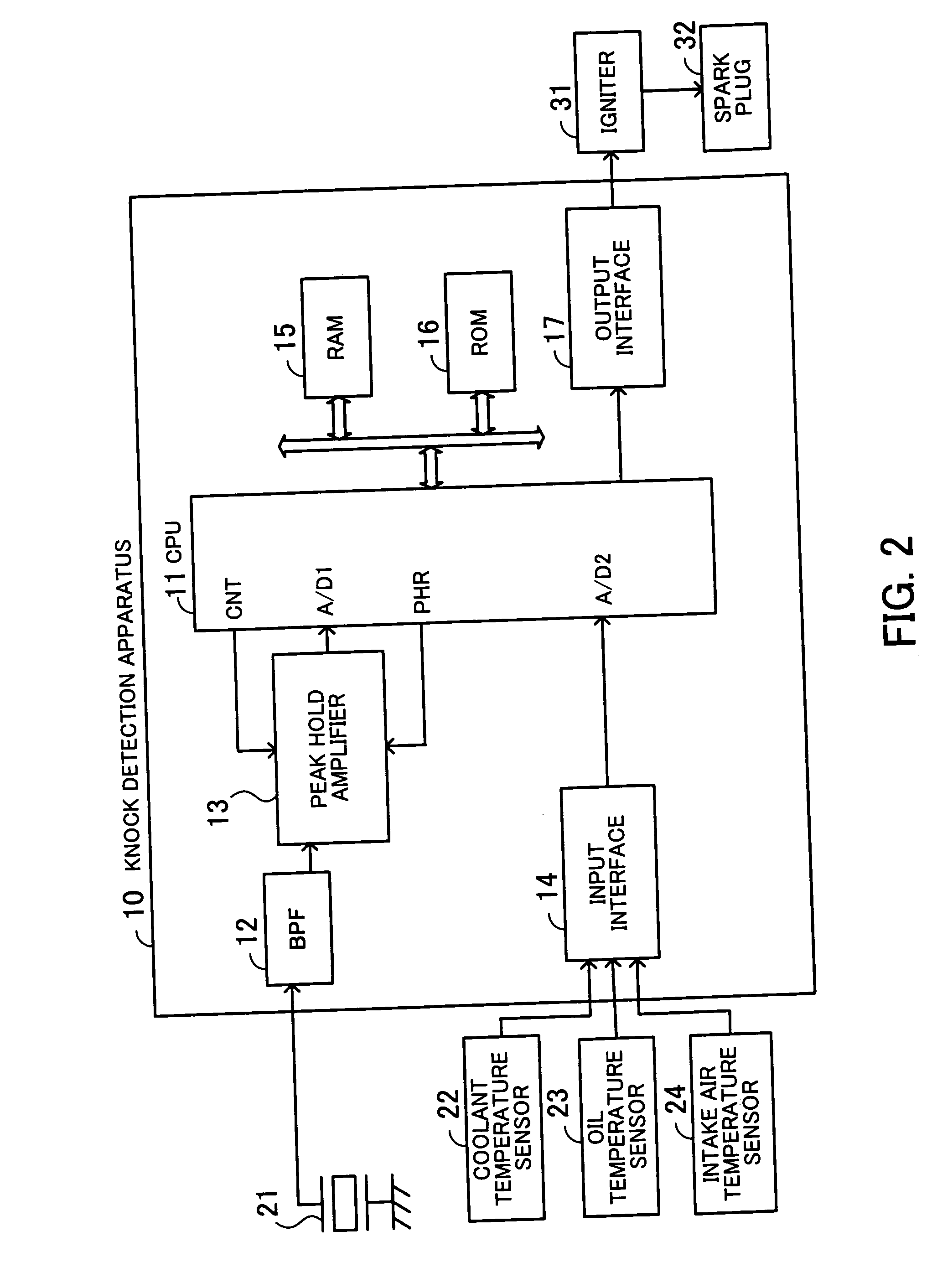
[0064] Next, a knock detection apparatus according to the present invention will be described in detail with reference to FIG. 2.
[0065]FIG. 2 is a block diagram of the configuration of the knock detection apparatus according to the first embodiment. As shown in FIG. 2, the knock detection apparatus 10 is comprised of a CPU 11, a BPF 12, a peak hold amplifier 13, an input interface 14, a RAM 15, a ROM 16, an output interface 17. The knock detection apparatus 10 is connected to a knock sensor 21, a coolant temperature sensor 22, an oil temperature sensor 23, and an intake air temperature sensor 24. Further, an igniter 31 connected to each spark plug 32 is connected to the knock detection apparatus 10.
[0066] The knock sensor 21 is a vibration sensor for converting engine vibration into an electric signal. The knock sensor 21 is formed e.g. by a piezoelectric element and is fixed to an engine cylinder block or the like.
[0067] An electric signal output from the knock sensor 21 is input...
sixth embodiment
[0177] Next, a knock detection apparatus according to the present invention will be described in detail with reference to drawings. First, the principles of the knock detection apparatus will be explained.
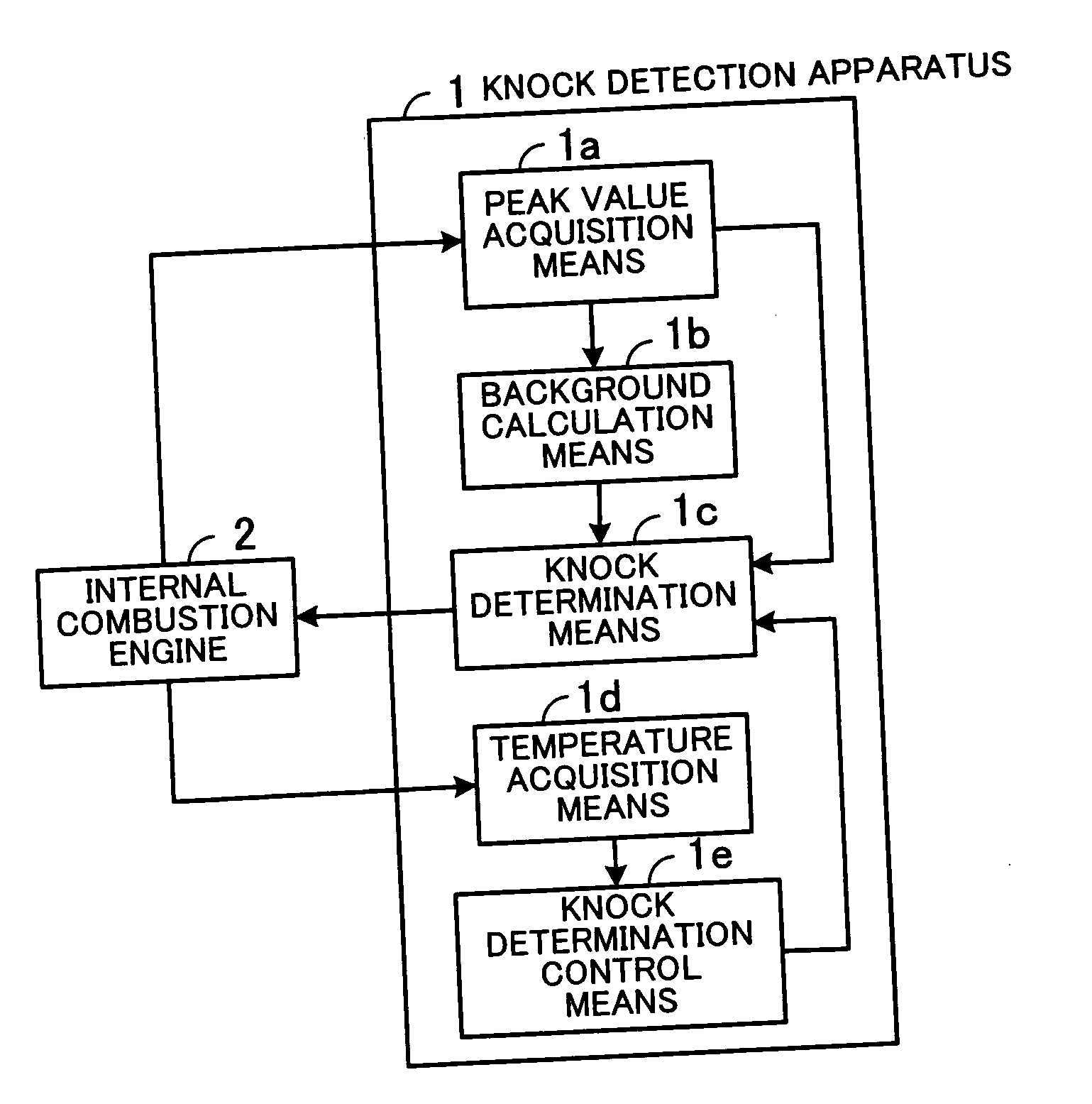
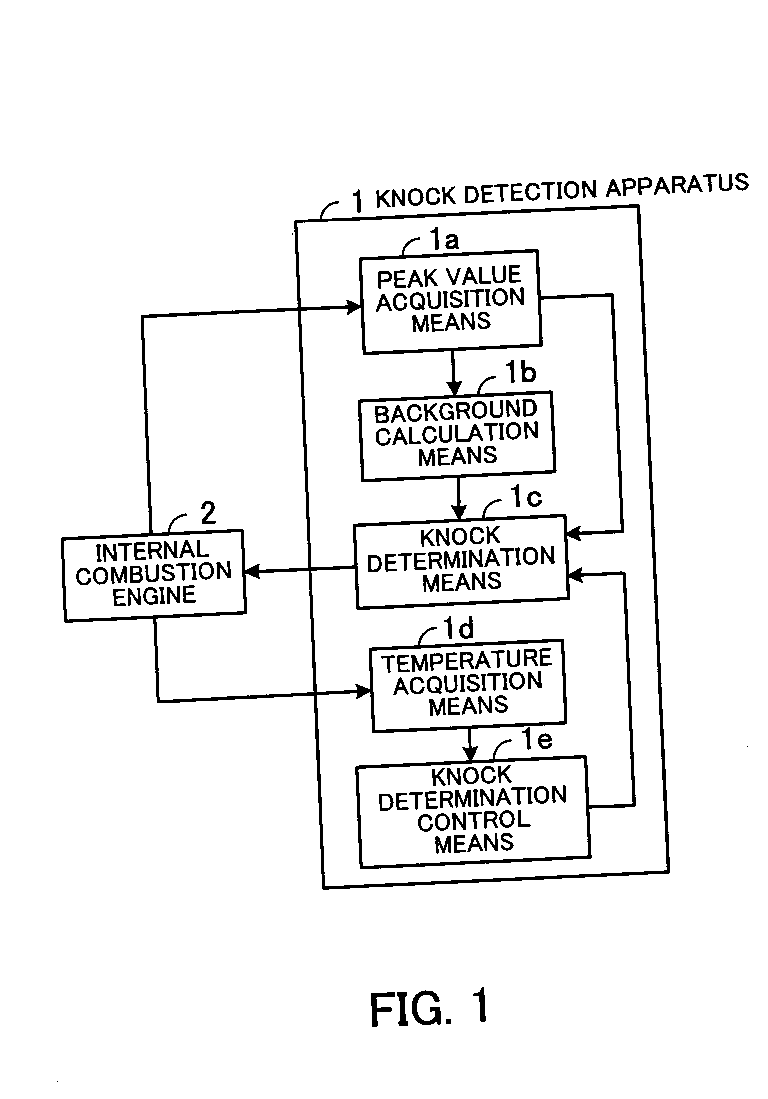
[0178]FIG. 21 is a diagram showing the outline of the knock detection apparatus. As shown in FIG. 21, the knock detection apparatus 101 is comprised of a peak value acquisition means 101a, a background calculation means 10b, a knock determination means 10c, a background setting means 101d, and a background storage means 101e. The knock detection apparatus 101 performs knock feedback control by controlling the ignition timing of an internal combustion engine 102.
[0179] The peak value acquisition means 101a acquires a peak value (knock signal) indicative of vibration of the engine 102 during a predetermined period of a rotation cycle of a crankshaft of the engine 102. For example, a knock sensor for detecting vibration is fixed to the engine 102, and the peak value acquisition means...
seventh embodiment
[0231] However, a peak value can be suddenly changed by a cause other than noise. For example, a change in engine speed or intake pipe pressure might cause a sudden change in the background. In this case, although quick convergence of the background to the peak value is desired, the update guard value retards the convergence. To eliminate this inconvenience, in the prior art, the update guard value is configured to be updated in accordance with a change in each of engine speed and intake pipe pressure, whereby convergence of the background is improved. The seventh embodiment is distinguished from the prior art in that the update guard value is configured to be updated in accordance with changes in the injection amount of fuel and the degree of opening of a throttle valve as well.
[0232] The configuration of a knock detection apparatus according to the seventh embodiment is substantially the same as that of the knock detection apparatus 110 shown in FIG. 22, except that a sensor for d...
PUM
 Abstract
Description
Claims
Application Information
PatSnap Eureka turns technology decisions into work you can execute. Powered by our Innovation Knowledge Graph, it runs expert workflows across engineering, life sciences, materials and intellectual property. Get your review-ready output in minutes.


