Receiver tank for a condensor and method of manufacturing the same

a condenser and receiver tank technology, applied in the field of condensers in air-conditioning systems, can solve the problems of increasing the cost of the vehicle air-conditioner, and the solution offered by these patents also has limitations, so as to reduce the cost of manufacturing, reduce the waste of resources, and avoid the effect of expensive and complicated tooling

Inactive Publication Date: 2006-06-15
SUBROS
View PDF1 Cites 17 Cited by
  • Summary
  • Abstract
  • Description
  • Claims
  • Application Information

AI Technical Summary

Benefits of technology

[0013] The invention provides for an improved receiver tank for a condenser that allows for ease in manufacturing.
[0014] The invention provides for an improved receiver tank for a condenser that does not require expensive and complicated tooling.
[0015] The invention provides for an improved receiver tank for a condenser that provides for savings in cost and...

Problems solved by technology

However, a common drawback with the typical air-conditioning system is that the refrigerant leaving the condenser is not always in the completely liquid phase.
Furthermore, the manufacture, part control, and assembly work of the connecting means between the condenser and the receiver-tank is required, which eventually increases the cost of the vehicle air-conditioner.
However, the solutions offered by these patents also have limitations.
However, the brazing of those members, especially the receiver tank is difficult, because they are each in the form of a cylinder that is large in thermal capacity.
In the above-described members the first header pipe and receiver tank are both large in thermal capacity, and therefore the brazing of those members is rather difficult.
That is, the members are increased in temperature slowly when compared with the other members; i.e. the melting of the brazing material on at least one of the two members takes time so that the resultant brazing of the two members is liable to be unsatisfactory.
In addition, the time required for those members to be connected to each other by brazing is unavoidably long; i.e. the assembling work of the receiver tank and the condenser is low in work efficiency.
Since the header and the receiver tank are cylindrical, the conta...

Method used


Image

  • Receiver tank for a condensor and method of manufacturing the same
  • Receiver tank for a condensor and method of manufacturing the same
  • Receiver tank for a condensor and method of manufacturing the same

Examples


Embodiment Construction

[0059] For the purpose of promoting an understanding of the principles of the invention, reference will now be made to the embodiment illustrated in the drawings and specific language will be used to describe the same. It will nevertheless be understood that no limitation of the scope of the invention is thereby intended, such alterations and further modifications in the illustrated device, and such further applications of the principles of the invention as illustrated therein being contemplated as would normally occur to one skilled in the art to which the invention relates.

[0060] Through out the patent specification, a convention employed is that in the appended drawings, like numerals denote like components.

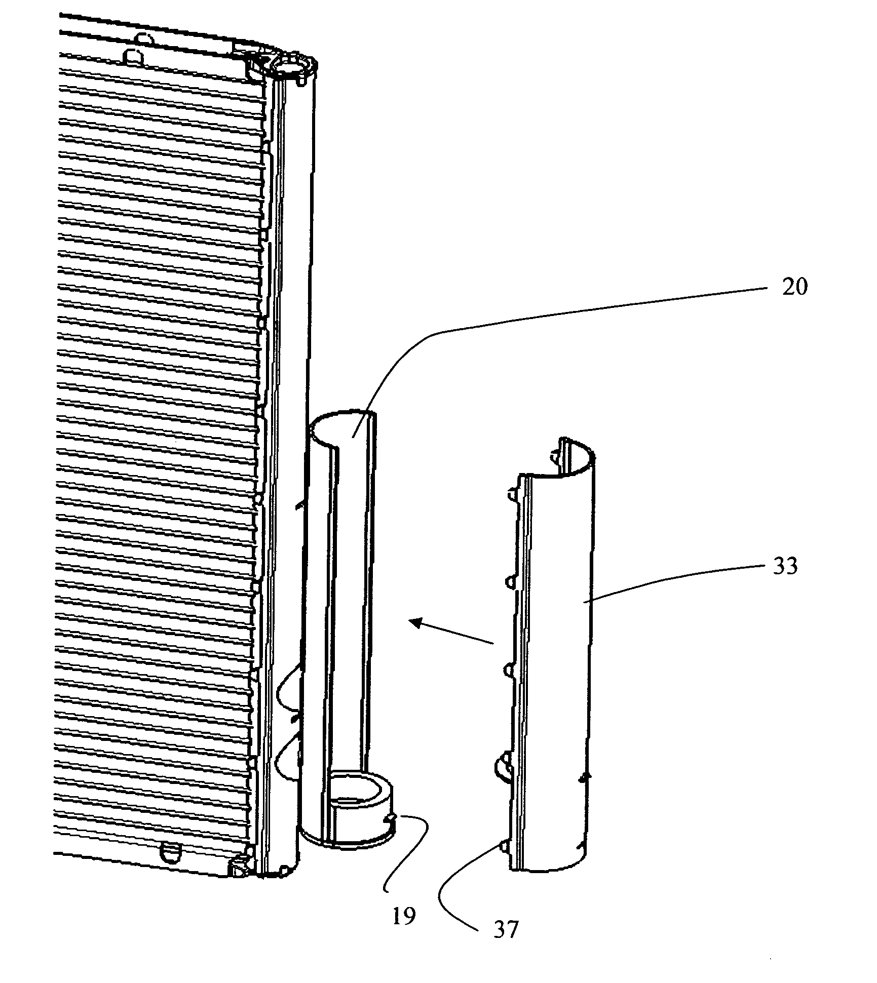
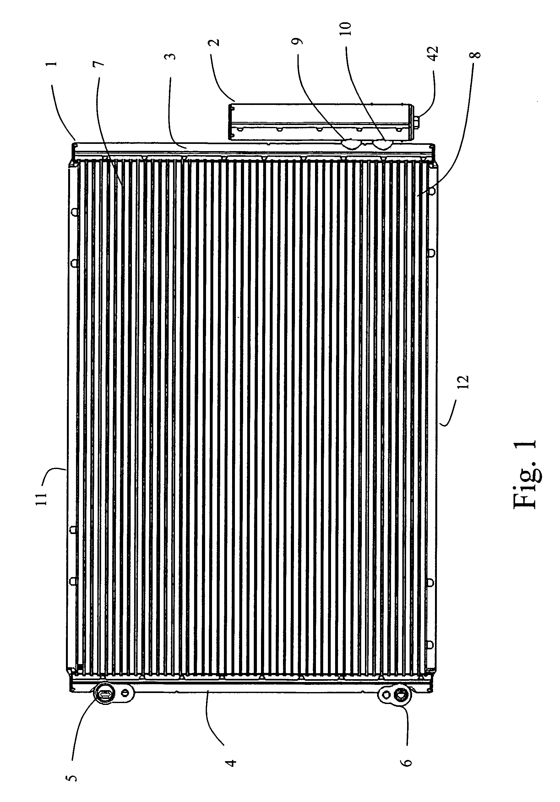
[0061] With reference now to FIG. 1, an integrated condenser (1) with the receiver tank (2) in accordance with the first embodiment of the invention is shown. The condenser has a pair of vertically oriented headers (3,4) horizontally spaced apart from each other. Each header...


PUM


Abstract

The invention provides for a receiver tank for an automobile air conditioner condenser comprising: a first half having two openings for refrigerant inlet and outlet, a second half to be joined with the first half to form the receiver, at least one of the first or second half having means to join with the other half.

Description

CROSS-REFERENCE TO RELATED APPLICATIONS [0001] This application claims priority of Indian Application No. 2463 / DEL / 2004, filed Dec. 10, 2004. FIELD OF INVENTION [0002] The invention relates to condensers in an air-conditioning system and more particularly condensers for automobile air-conditioners. [0003] At the outset, caulking as a process with reference to this invention refers to a joining process wherein two components are crimped, bent, or deformed at the joining juncture, without the use of any external filler material. Caulking is usually carried out prior to brazing in the brazing furnace to ensure that the components to be brazed are retained against each other. BACKGROUND OF THE INVENTION [0004] An air-conditioning system typically consists of the following components: a compressor, condenser, expansion valve and evaporator. The condenser receives high pressure, high temperature gaseous refrigerant from the compressor. The condenser is functional in condensing the refrige...

Claims


Application Information

Patent Timeline
IPC IPC(8): F25B39/04B23P17/00B21D51/18B21D53/02
CPCF25B39/04F25B40/02F25B2339/0441F25B2339/0442F25B2339/0446Y10T29/49396F25B2400/162F28F9/0246F28F9/0248F28F2220/00Y10T29/4935F25B2400/16
Inventor SHAH, RAMESH K.RAVI KUMAR, A. S.KARWALL, NIKHIL
Owner SUBROS
Why Eureka
Try Eureka