Powered aircraft including inflatable and rotatable bodies exhibiting a circular cross-section perpendicular to its rotation axis and in order to generate a lift force

Inactive Publication Date: 2006-06-15
SAEED TEHRANI OMID
View PDF25 Cites 3 Cited by
  • Summary
  • Abstract
  • Description
  • Claims
  • Application Information

AI Technical Summary

Benefits of technology

[0018] A still further advantage of the current invention is the usage of inflatable rotating bodies, in a preferred variant, and as opposed to rigid rotating bodies. The use of an inflatable rotating body is optional in the present invention, however makes possible the ability to deflate the rotating body structure when needed, thus rendering the aircraft small enough to be packed, kept or carried in a very small space and makes it ideal for personal usage, especially with easy and cheap shipping/handling due to small occupied volume. A still further advantage of the current invention is the ability to employ differently sized engines to rotate the lift force producing bodies, and also in generating thrust force, both of which can be controllable. It is also envisioned that a separate engine can be used for the conventional propulsion systems in addition to a dedicated engine for driving the rotating bodies. Along these lines, it is understood that the reducing ratio established between the engine(s) can be modified, such as in conventional automotive applications, to vary gear ratios for separately driving the rotating bodies, as opposed to, say, an aircraft propeller.
[0019] Yet another advantage of the current invention is that, by using an engine as an active and direct method to rotate the rotating bodies, it is possible to generate significant lift forces even at initial and low speed forward motion, making it more practical compared to the systems using other methods of rotation for rotating bodies, and such as using the flowing air to rotate the rotating bodies as set forth in the Zaparka design.
[0020] Yet another advantage of the current invention is faster acceleration in flight, caused by taking off sooner and due to the additional lift force generation by rotating the bodies with engine power, and thus reducing friction with the ground after takeoff, the lower drag forces once again being due to the swiping/bending backwards of the rotating bodies.
[0021] Another advantage of the current design of this invention is the provision of three different ways to neutralize reaction forces produced by the rotating bodies, in a reverse direction to their rotation, and which can cause the lift-producing machine to rotate in the opposite direction. These new mechanisms, used to neutralize the reaction force to the rotation of the rotating bodies, and which make the new design specific include 1) placing

Problems solved by technology

In such instances, there is no prediction for neutralizing of the reaction force to the rotation of the rotating bodies by the engine.
Additionally, the lack of engine power in those designs causes a low amount of lift force generation.
Problems associated with earlier rotating airfoil devices include the low efficiency of rotating bodies in comparison to the conventional airfoils in generating lift forces with the same degree of energy input.
A secondary problem includes the turbulent flow t

Method used


Image

  • Powered aircraft including inflatable and rotatable bodies exhibiting a circular cross-section perpendicular to its rotation axis and in order to generate a lift force
  • Powered aircraft including inflatable and rotatable bodies exhibiting a circular cross-section perpendicular to its rotation axis and in order to generate a lift force
  • Powered aircraft including inflatable and rotatable bodies exhibiting a circular cross-section perpendicular to its rotation axis and in order to generate a lift force

Examples


Embodiment Construction

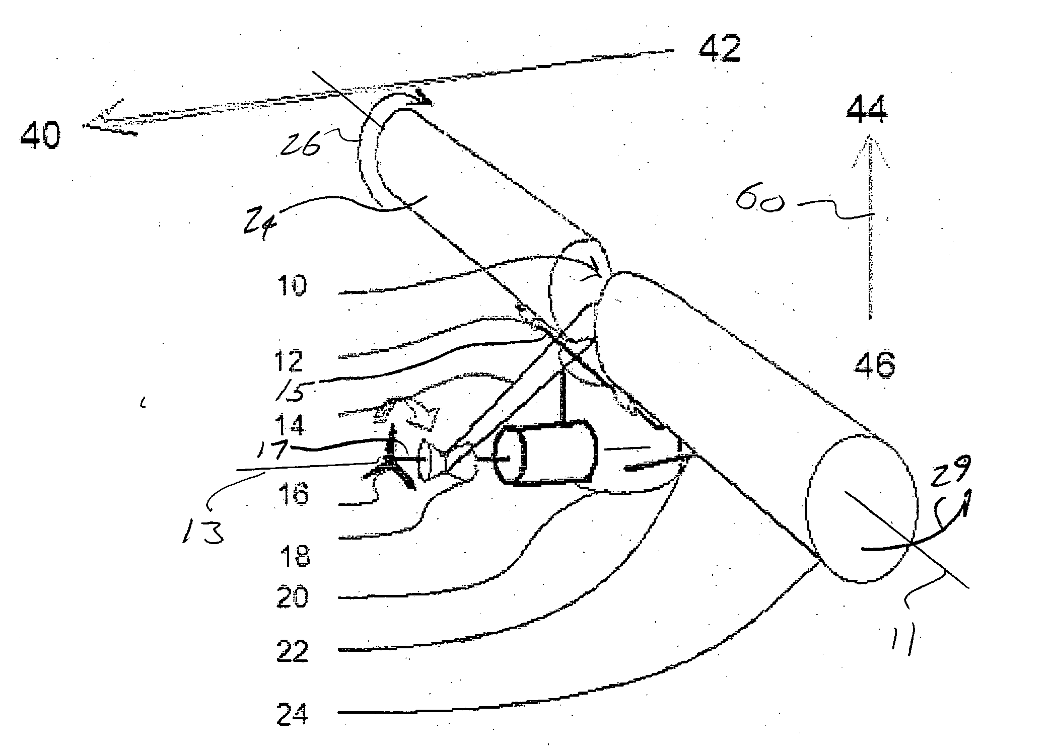
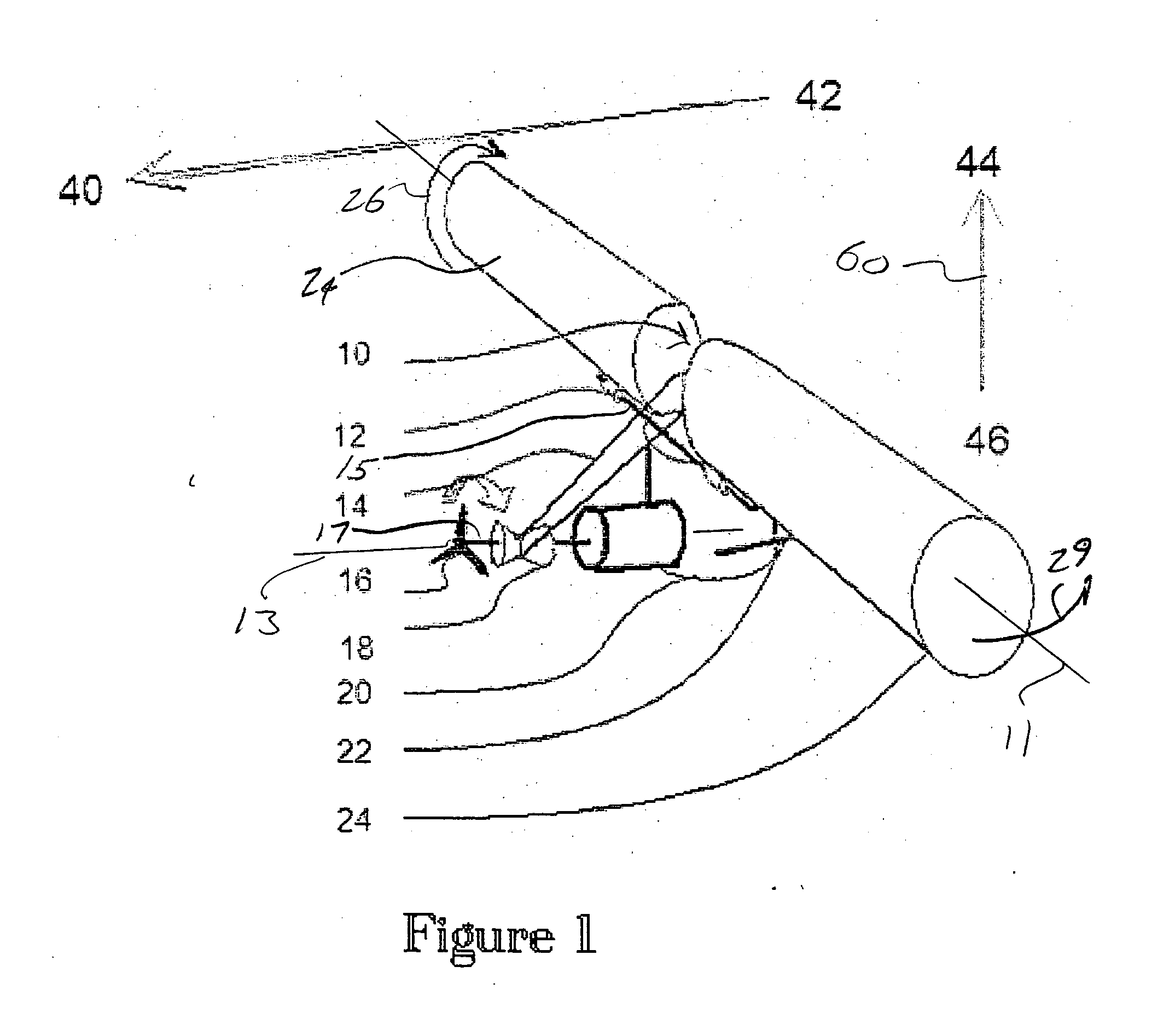
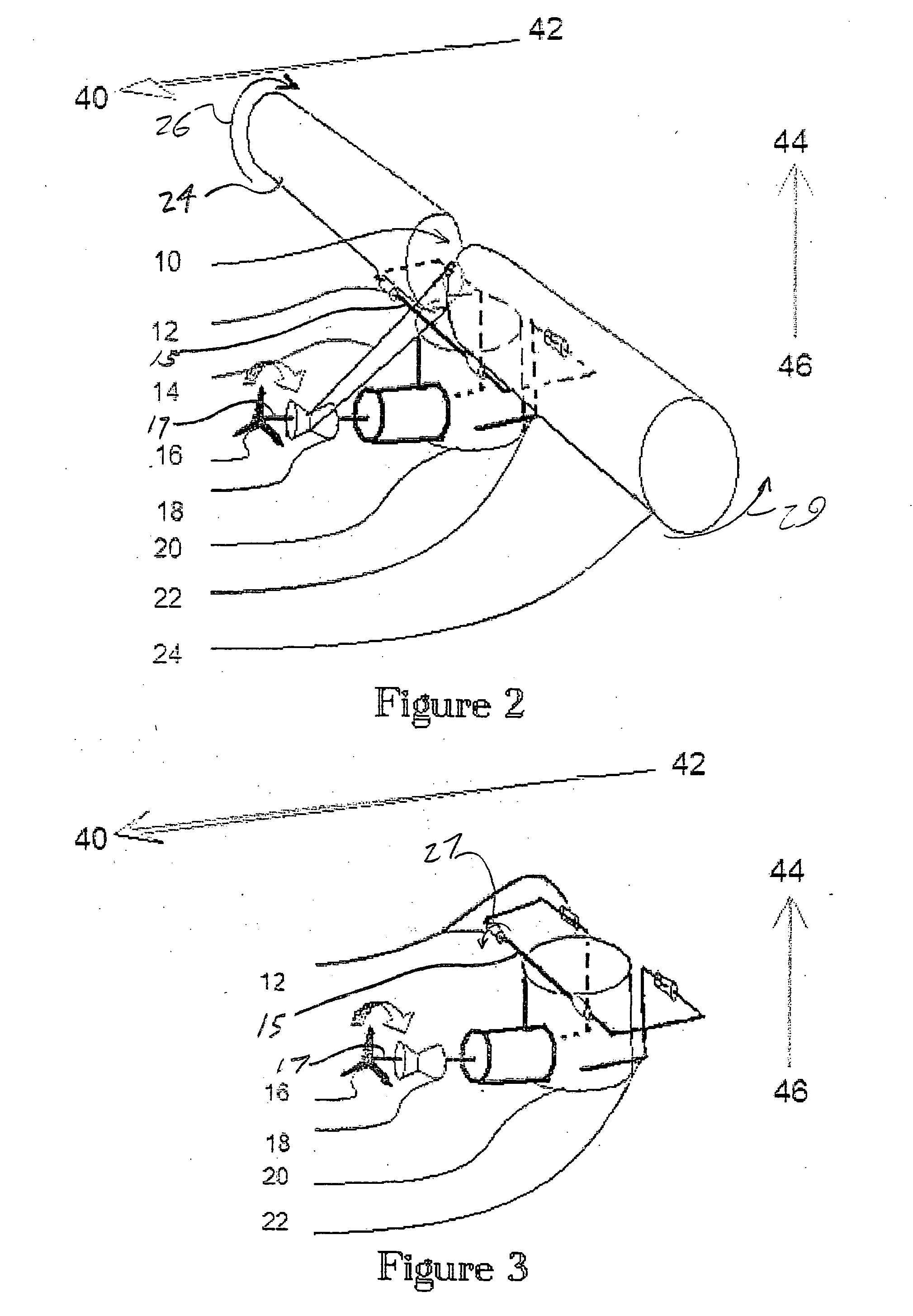
[0035] Referring now to FIGS. 1-10, several variants are illustrated of a powered aircraft 10 which is capable of creating a lift-generating force through the provision of a plurality of rotatably driven rollers and according to Magnus effect physical principles. In particular, the present invention discloses an improved lift-generating aircraft which overcomes many of the drawbacks associated with the prior art Magnus effect lift devices.

[0036] Referring to FIG. 1, a perspective illustration is shown of an arrangement of lift-generating components according to a first preferred embodiment of the present invention and which includes a pair of lift force producing rotating bodies (illustrated at 24 and as will be discussed in further detail), each exhibiting an elongated and crosswise extending circular cross-section through which extends a centerline and crosswise extending axis 11. As will be described in additional detail, the rotating cylindrical shaped bodies 24 are preferably ...


PUM


Abstract

A lift force generating aircraft having an engine and a thrust force producing device. A pair of elongated and rotating bodies, an axial centerline through the bodies extending in a direction substantially perpendicular to a fore to aft axis extending between the engine and thrust-producing device and at a location above a center of gravity associated with the engine and thrust-producing device. The rotating bodies being constructed of a material inflatable to a desired pressure. A rotary output associated with the engine rotating the bodies, causing them to deflect to angles lesser than the perpendicular with the fore to aft axis, and in response to air stream forces acting upon the bodies in order to reduce drag forces experienced on a rear side of the rotating bodies.

Description

CROSS REFERENCE TO RELATED APPLICATIONS [0001] The present application is a continuation-in-part of U.S. application Ser. No. 10 / 709,493, filed May 10, 2004, entitled “A Powered Aircraft Including Inflatable and Rotatable Bodies Exhibiting a Circular Cross-Section Perpendicular to Its Rotation Axis and In Order to Generate a Lift Force”.BACKGROUND OF INVENTION [0002] 1. Field of the Invention [0003] This invention relates generally to aerodynamics and flight dynamics devices. More particularly, the present invention teaches a powered aircraft device incorporating substantially cylindrical shaped and power rotated components for creating lift. Specifically, the current invention significantly reduces poor fuel economy and problems of acceleration to higher speeds associated with prior art Magnus effect rotor airfoils, by significantly decreasing drag forces associated with such acceleration. [0004] 2. Discussion of the Prior Art [0005] The present invention operates from the physics ...

Claims


Application Information

Patent Timeline
IPC IPC(8): B64C39/00B64C27/00
CPCB64C3/30B64C3/56B64C23/02B64C39/005Y02T50/145Y02T50/10
Inventor TEHRANI, OMID SAEED
Owner SAEED TEHRANI OMID
Why Eureka
Try Eureka