Air bearing compatible with operation in a vacuum

a technology of air bearings and vacuum chambers, which is applied in the direction of photomechanical equipment, instruments, optical radiation measurement, etc., can solve the problems of reducing the vacuum level in the vacuum chamber, affecting the design of the wafer stage for use in the electron beam projection system, and affecting the accuracy of the lithography results. , to achieve the effect of reducing the number of hoses needed for the linear guide and high vacuum levels

Inactive Publication Date: 2006-06-15
NIKON CORP
View PDF15 Cites 16 Cited by
  • Summary
  • Abstract
  • Description
  • Claims
  • Application Information

AI Technical Summary

Benefits of technology

[0012] The present invention relates to air bearing linear guides which have a stroke length that is substantially independent of a length associated with the air bearing linear guides, and are suitable for use in an environment with high vacuum levels. Moreover, the number of hoses needed by the linear guide may be substantially minimized. According to one aspect of the present invention, a guide bearing system includes a linear guide and a first guide beam. The linear guide has an inner surface which includes an air pad. The linear guide is wrapped around the first guide beam such that it may slide with respect to the guide beam. The guide beam includes a first chamber that is in fluid communication with the linear guide through at least one of a first plurality of ports in the guide beam which enable access to the first chamber.
[0014] The use of multiple ports on a common surface of a guide beam enables the stroke length associated with a linear guide to be increased without increasing the size of the linear guide and, hence, the size of an overall apparatus which includes the linear guide. As the linear guide moves from one port to another, a mechanism such as a valve mechanism may open and close the ports as appropriate to allow pumping and to reduce the amount of gas that escapes from the interior of the guide beam. A port that is overlapped by the linear guide is generally open to enable appropriate areas of the linear guide to be in fluid communication with the interior of the guide beam, while ports that are not overlapped by the linear guide or are only partially overlapped by the linear guide are generally closed to substantially prevent gas from escaping from the guide beam.

Problems solved by technology

The design of a wafer stage for use in an electron beam projection system may be complicated, as an electron beam projection system generally must not include moving magnets or metals which alter the magnetic field associated with the electron beam projection system and, hence, the electron beam.
Electron beam projection systems generally include a lens system that may dynamically move a projection image to follow a stage, which is generally not possible with other systems, e.g., an optical system, as will be appreciated by those skilled in the art.
In addition, electron beam lens systems typically correct for relatively small errors in relative stage positions, whereas optical systems generally do not.
As will be appreciated by those skilled in the art, however, conventional air bearings often leak.
In some cases, air flow leakage into a vacuum chamber from an air bearing guide may significantly reduce the vacuum level in a vacuum chamber.
In general, in addition to electron beam projection systems which include wafer stages and reticle stages which may operate in a vacuum environment, there are many other types of systems which operate in a vacuum environment, and, as a result, may not operate as desired when conventional air bearings associated with the systems leak.
One source of motion perturbation of stages is drag and vibration from hoses and electrical cables attached to the stage.

Method used


Image

  • Air bearing compatible with operation in a vacuum
  • Air bearing compatible with operation in a vacuum
  • Air bearing compatible with operation in a vacuum

Examples


Embodiment Construction

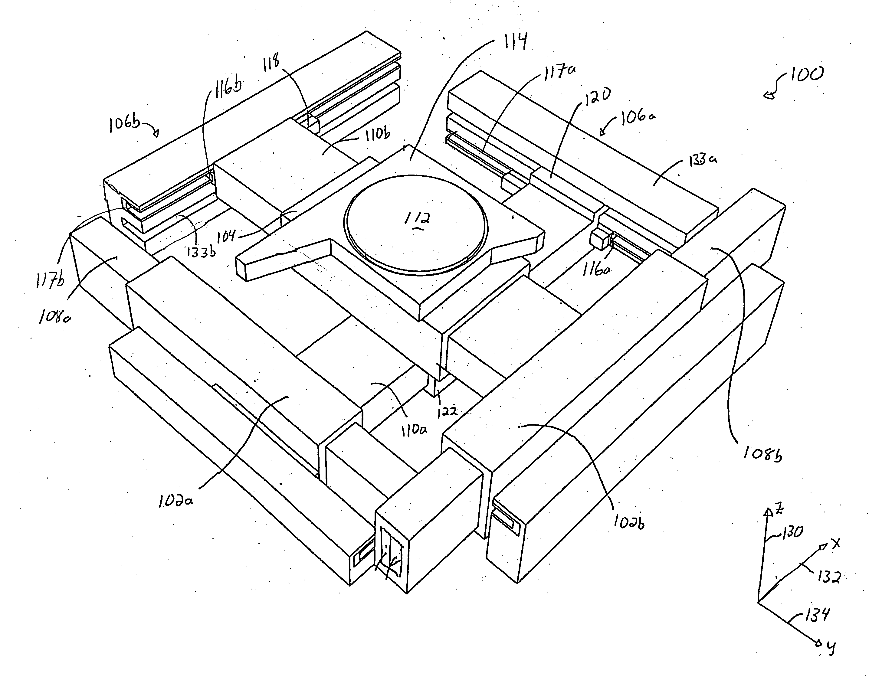
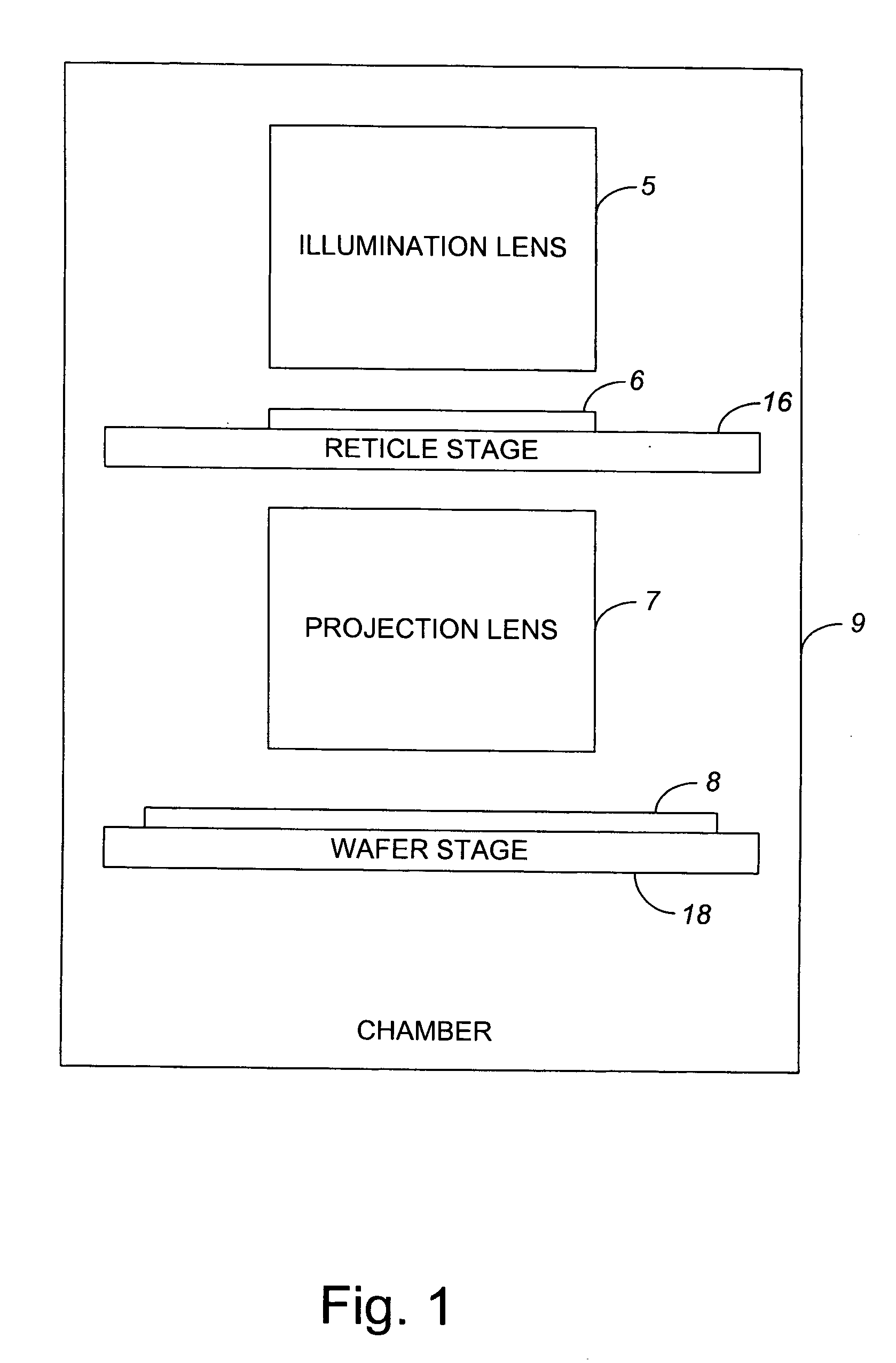
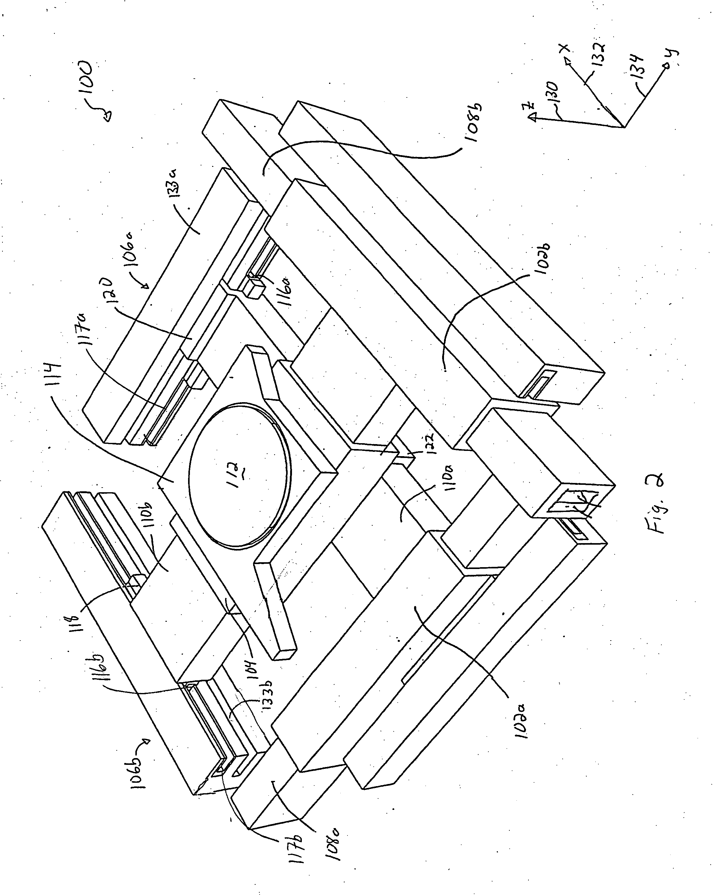
[0044] The configuration of a wafer stage or reticle stage which is suitable for use in a lithography apparatus such as an electron beam projection lithography system generally may not include conventional air bearings, as conventional air bearings typically leak. The leakage of air from air bearings into a vacuum chamber associated with an electron beam projection system would likely significantly increase the residual gas pressure in a vacuum chamber, thereby adversely affecting an overall electron beam lithography process. Since a conventional air bearing typically leaks at a flow rate many orders of magnitude above an acceptable level for an electron beam projection system, the use of a conventional air bearing may result in inaccuracies in photolithography processes.

[0045] An air bearing linear guide which does not leak a significant amount may be used in a vacuum chamber. Such an air bearing linear guide may generally include air flow evacuation stages which are incorporated ...


PUM

PropertyMeasurementUnit
gap distanceaaaaaaaaaa
pressureaaaaaaaaaa

Abstract

Methods and apparatus for enabling the stroke length of a linear guide that is suitable for use in an environment with high vacuum levels to be substantially independent of a length associated with the linear guide are disclosed. According to one aspect of the present invention, a guide bearing system includes a linear guide and a first guide beam. The linear guide has an inner surface which includes an air pad. The linear guide is wrapped around the first guide beam such that it may slide with respect to the guide beam. The guide beam includes a first chamber that is in fluid communication with the linear guide through at least one of a first plurality of ports in the guide beam which enable access to the first chamber.

Description

BACKGROUND OF THE INVENTION [0001] 1. Field of Invention [0002] The present invention relates generally to semiconductor processing equipment. More particularly, the present invention relates to a stage for use in a lithography system requiring a controlled environment, such as a vacuum. Such systems include an electron beam projection lithography system and an extreme ultraviolet (EUV) lithography system. [0003] 2. Description of the Related Art [0004] Lithography processes are integral to the fabrication of wafers and, hence, semiconductor chips. Future systems used for lithography are expected to include electron beam projection systems which project electron beams of finite area through a patterned reticle, as well as extreme ultraviolet (EUV) lithography systems. The reticle effectively serves as a template for a corresponding pattern on a wafer. For an electron beam projection system, a relatively broad beam of electrons may be collimated and provided to a reticle, which may b...

Claims


Application Information

Patent Timeline
Patent Type & Authority Applications(United States)
IPC IPC(8): G01N23/00
CPCF16C29/025F16C32/0603F16C2300/62G03F7/70716G03F7/70816G03F7/70841
Inventor SOGARD, MICHAEL REID
Owner NIKON CORP
Why Eureka
Try Eureka