Collector sump cooling tower

a cooling tower and collector technology, applied in the direction of trickle coolers, machines/engines, combustible gas purification/modification, etc., can solve the problems of affecting the operation of the cooling tower, the risk of above-grade elements freezing, and the surrounding property, so as to reduce energy consumption, simplify the operation, and eliminate the risk of freezing

Inactive Publication Date: 2006-06-15
X NTH INC
View PDF27 Cites 7 Cited by
  • Summary
  • Abstract
  • Description
  • Claims
  • Application Information

AI Technical Summary

Benefits of technology

[0012] The present invention offers a cooling tower apparatus and method that eliminates freezing risks, simplifies operation, reduces energy consumption and increases reliability of a cooling tower.

Problems solved by technology

One drawback of the above prior art is a potential for the above grade elements to freeze during cold weather conditions.
Both the build up of ice and ice breaking off the cooling tower and falling can cause injury or property damage to the cooling tower (10) and any surrounding property.
Additionally, the expansion force of ice formed within the cooling tower has the potential to fracture the cooling tower's components (10).
Any or all of these events can drastically disrupt the function of the cooling tower (10) and, more importantly, catastrophically affect the productivity levels of the work facility.
These insulation or heating mechanisms represent an additional cost to the facility and are not completely efficient at preventing ice formation.
However, freeze protection risks remain with FIG. 2's prior art design where the warm water return piping (150) is exposed to external temperatures when it exits the ground to return to the cooling tower from the facility.
These components are susceptible to freezing because water can be trapped within these pipes when the valves are rotated to either the normal setting, wherein the warm water returns to the nozzle (15), or in the by-pass setting, wherein the warm water is returned to the sump (125).
Freezing of the water within these pipes can lead to freezing and even destruction of the cooling tower components.
Although, the by-pass valve (155), the by-pass balancing valve (140) and the stand-pipe riser (145) may be insulated or heated to prevent such ice formation, these insulation or heating mechanisms represent an additional cost to the facility and are not completely efficient at preventing ice formation.
This colder supply water dramatically reduces the energy needed to operate the facility.
However, one significant problem with lowering the sump water temperature is freezing.

Method used


Image

  • Collector sump cooling tower
  • Collector sump cooling tower
  • Collector sump cooling tower

Examples


Embodiment Construction

Technical Details

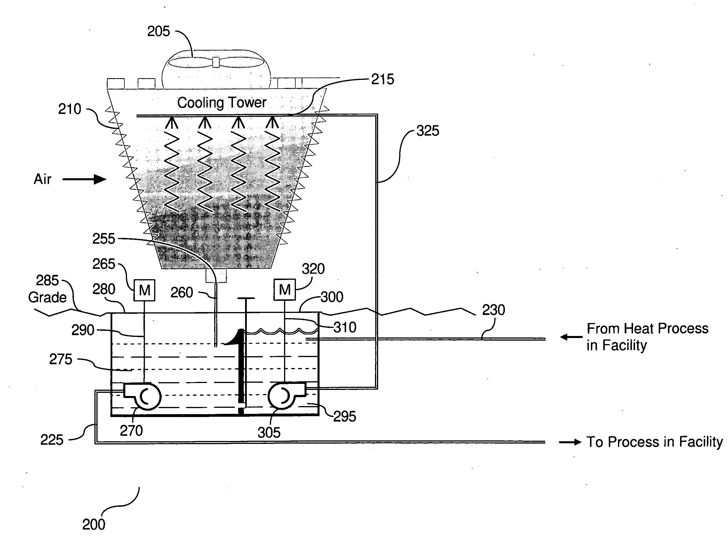
[0022] Turning now to the preferred embodiment, FIG. 3 is an illustration of the preferred embodiment of the water cooling tower (200). The embodiment shown in FIG. 3 includes an above grade cooling tower fan (205), an above grade fill (210), and an above grade nozzle or hot pan (215). These three components may be arranged in various configurations to enhance getting water distributed on the fill (210) so that air flow from the fan (205) can cause accelerated evaporation. For example, in some cases the water drips down through the fill (210) and the fan air is pulled up; counterflow. In other systems the water drips down through the fill (210) and the air moves across sideways; crossflow. Some systems use fine spray nozzles under pressure, others use holes in the bottom of a long flat pan to distribute the water. Many cooling towers use fans mounted low that force air up through the fill; forced draft. Other towers use fans on the top that pull the air up; induced...


PUM

PropertyMeasurementUnit
heightaaaaaaaaaa
volumeaaaaaaaaaa
mixingaaaaaaaaaa

Abstract

The present invention relates to a cooling apparatus and method wherein a supply sump and turbine are below grade. Water cooled from an above grade cooling tower fan and fill flows into the supply sump and is pumped through below grade pipes into a facility. Heat rejected water from the facility then flows through below grade pipes into a below grade collector sump. A collector sump pump pumps the heat rejected water above grade into a nozzle and back into the fill to be cooled. The present invention is constructed such that water is not idle in any above grade component. Accordingly, the risk of water freezing within the above grade components is drastically reduced. Moreover, the heat rejection water can by-pass all above grade components and travel directly into the supply sump in the event of reduced load from the facility.

Description

CROSS REFERENCE TO RELATED APPLICATION(S) [0001] This is a non-provisional utility patent application claiming benefit of the filing date of U.S. provisional application Ser. No. 60 / 635,261 filed Dec. 10, 2004, and titled COLLECTOR SUMP COOLING TOWER.BACKGROUND OF THE INVENTION [0002] 1. Technical Field [0003] The present invention relates to an evaporative cooling tower. More specifically, the invention relates to an improvement to the cooling tower that protects exposed components from elements that may affect reliability and productivity. [0004] 2. Description of the Prior Art [0005] Many large industrial processes and laboratories, such as manufacturing plants, convention centers, hospitals, military command centers, and the like, operate 24 hours a day, 7 days a week, every week of the year. In many cases, the economic security, the public health, the public welfare, and the national security of our nation are all dependant upon the continued operation of these facilities. Addi...

Claims


Application Information

Patent Timeline
Patent Type & Authority Applications(United States)
IPC IPC(8): B01F3/04
CPCF28C1/04F28C3/08F28F19/006F28F25/02Y10S261/11Y02B30/70
Inventor KOPLIN, EDWARD C.
Owner X NTH INC
Why Eureka
Try Eureka