Sealing device for filtration devices

a technology of sealing device and filtration device, which is applied in the direction of membranes, filtration separation, separation process, etc., can solve the problems of insufficient seal type, leakage, and expensive equipment, and achieves the effect of reducing the risk of leakage, avoiding leakage, and avoiding leakag

Inactive Publication Date: 2006-06-15
MILLIPORE CORP
View PDF17 Cites 18 Cited by
  • Summary
  • Abstract
  • Description
  • Claims
  • Application Information

AI Technical Summary

Benefits of technology

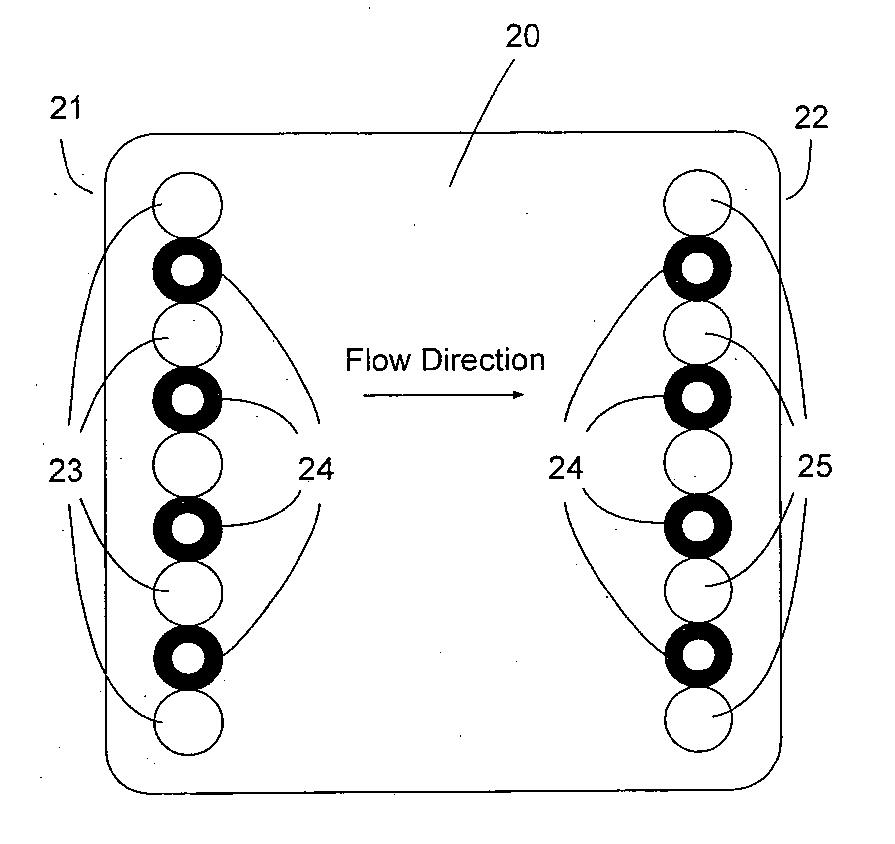
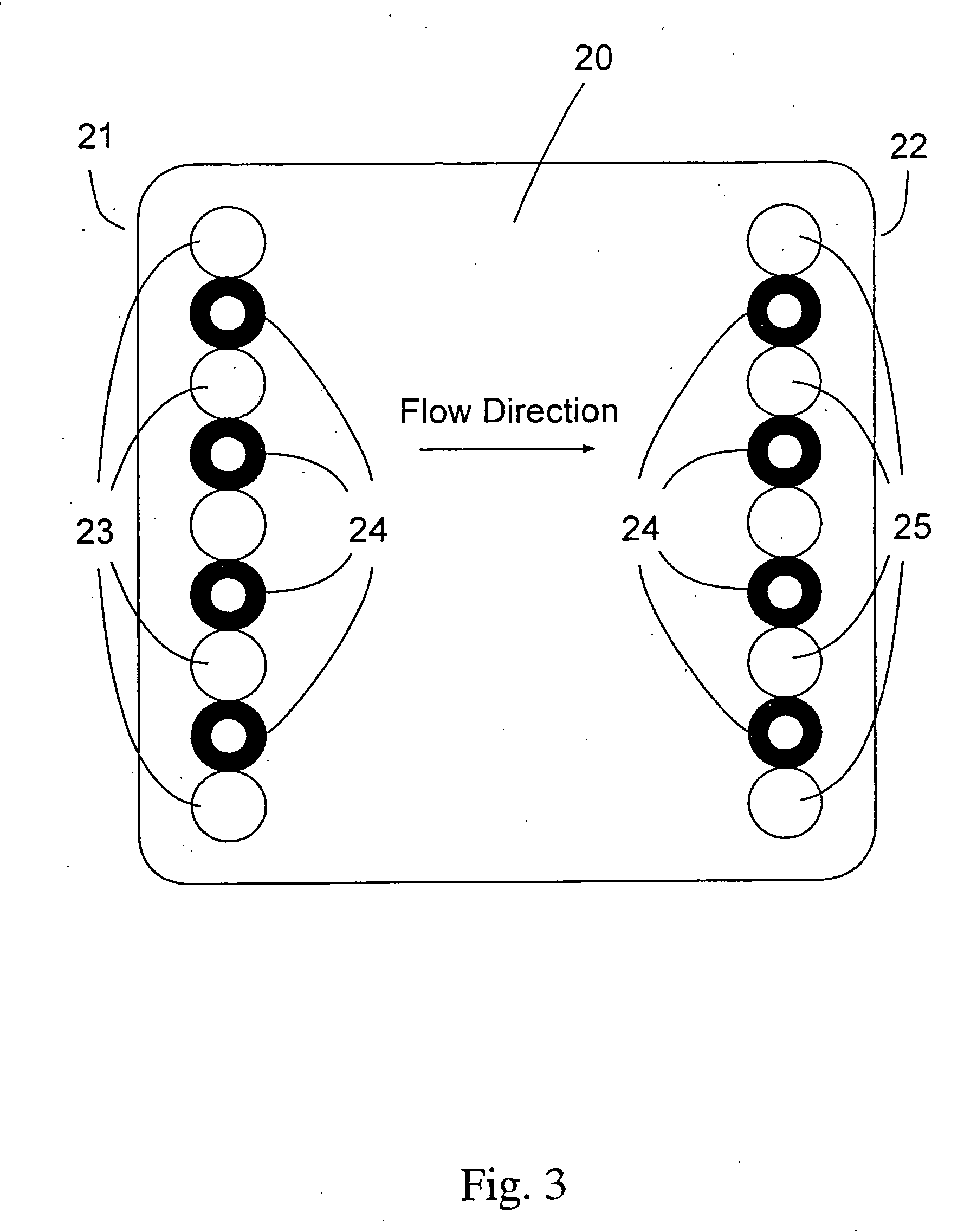
[0017] The present invention relates to the formation of a seal around a filtration element to be sealed, such as one or more fluid ports in a filtration module. The use of thermoplastic materials, especially those that can be molded, preferably injection molded in place are preferred as it forms an integral, sanitary gasket or seal. The claimed materials are low in extractables and absorption / desorption of filtration fluids making them cleaner to use and ensuring that the sealing material does not add or remove any constituent of the fluid being filtered other than that desired by the filter action of the device (such as particulates, bacteria and viruses). Moreover, in the preferred molded in place embodiments, it prevents the seal from moving or be being improperly aligned upon sealing ensuring that the seal is always consistently the same. Lastly, when using it in the preferred molded in place embodiments, the seal has no dead space behind it in which microorganisms might otherwise grow.
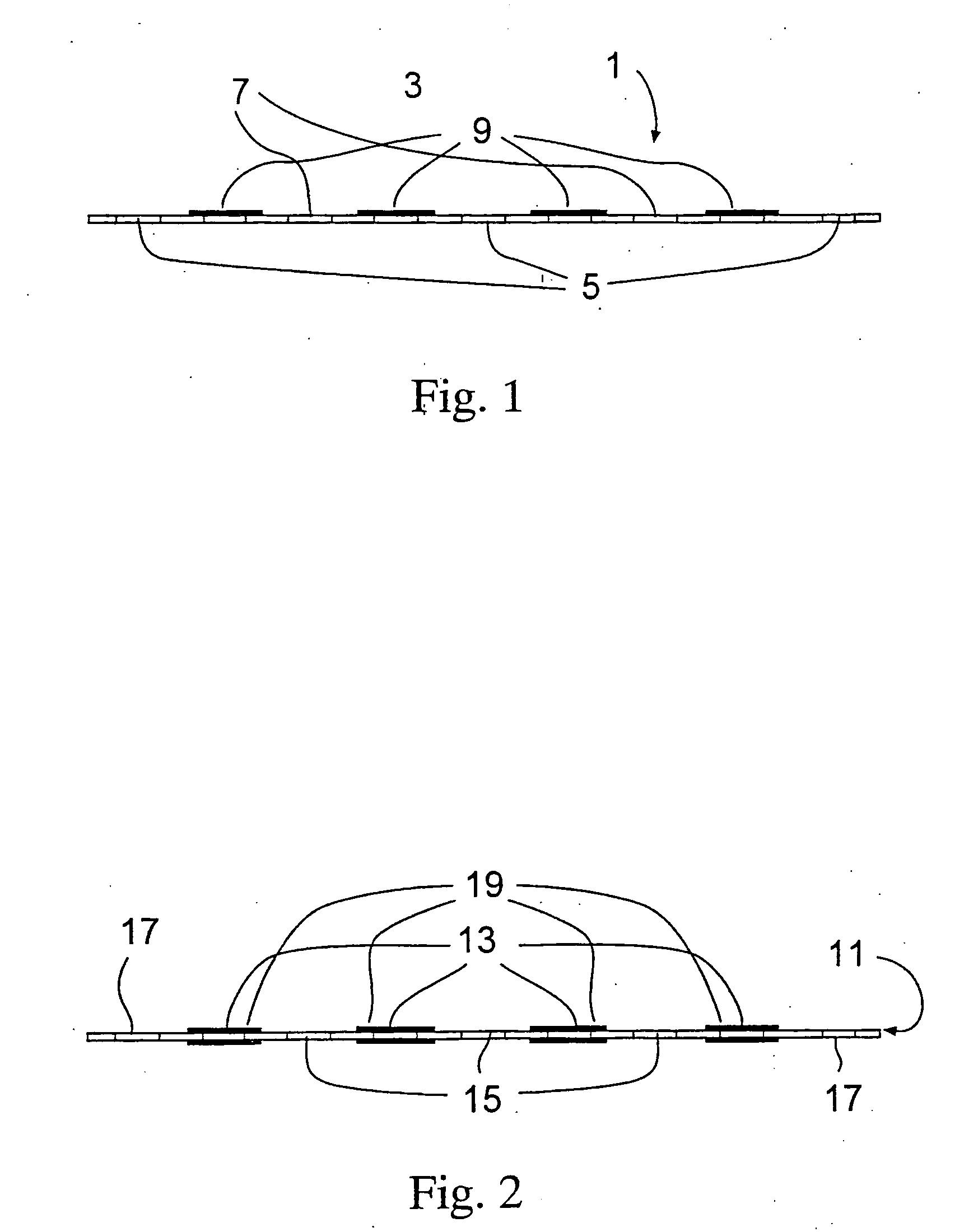
[0018] In a cassette device, the seal is formed on at least one side and preferably on both sides of the component such as a screen and is proud of or raised above the surface of the component. Preferably, the seal is molded to the component, more preferably it is injection molded to the component. The seal maybe formed of any elastomeric material such as a thermoplastic polymer, copolymer or terpolymer, thermoplastic elastomers, thermosets such as urethane, especially closed cell foamed urethane, and rubber, both natural and synthetic. The molded seal provides better sealing, allows for a variation in heights and geometries, in cassettes the use of more open screens, in some cases the elimination of a screen per se via the use of a molded rim of seal which forms an open space which acts as the screen and provides better cleanliness and lower extractables than the currently used adhesives.

Problems solved by technology

However, to use these modules one needs to acquire new manifold equipment that is an expensive capital investment.
However, in some processes this type of seal is not sufficient.
For example where the process calls for the use of alternating of hot and cold fluid cycles, it has been found that the seal is often insufficient and tends to leak.
Likewise, when using compressible membranes such as reinforced composite cellulosic membranes, especially at higher pressures (>50 psi), the seal fails due to the compression of the membrane by the pressure of the fluid which allows for leakage.
In all three formats, the above methods of providing a seal or gasket have been less then satisfactory.
Adhesives are undesirable since they have limited chemical compatibility, are a source of significant extractable species, introduce process control difficulties, impose bond strength limitations, impose use temperature limitations and increase process cycle time.
Direct heat sealing wherein a heating element contacts a material which flows to form a seal is undesirable since its use imposes a limitation upon the thickness of the material being heat sealed.
This results in a material reduction of the number of layers that can be present in a given volume of the filtration device, thereby undesirably reducing the filtration capacity of the device.
In addition, direct heat sealing is undesirable because it requires multiple steps, imposes material compatibility limitations and requires a substrate to effect direct heat sealing of filtration elements.
Solvent bonding is undesirable since solvents impose environmental limitations on liquids to be filtered.
In addition, the use of materials such as polysilicone based materials as sealing materials, O-rings or gaskets is undesirable as they absorb a portion of a feed being filtered into their structure and then allow the absorbed material to be desorbed into subsequently filtered samples thereby contaminating them.
Additionally, these free standing gaskets often fall out of the device during installation or repair or replacement and often are improperly seated which causes them to leak.
Moreover, loose fitting seals such as O-rings create dead space behind the gasket sealing surface (such as between the inner wall of the O-ring and the wall of the filter housing to which it is attached).
This dead space is a breeding ground for bacteria, molds, viruses and yeasts, all of which compromise the sterility and integrity of the seal and the filtration device.

Method used


Image

  • Sealing device for filtration devices
  • Sealing device for filtration devices
  • Sealing device for filtration devices

Examples


example 1

[0064] A TFF module was made with a feed screen having an injection molded thermoplastic elastomeric gasket made from Santoprene® 80 durometer elastomer and 0.005 inch in height from each side of the screen. One layer of a composite regenerated cellulose membrane, PL composite, a relatively easily compressible membrane available from Millipore Corporation, was used in the module.

[0065] A comparison module, known as a PELLICON® Maxi cassette, available from Millipore Corporation of Bedford, Mass. was constructed similarly to the one above, except that the feed screen seal of standard epoxy was used. This seal was flush with the surface of the screen.

[0066] Both were tested in a PELLICON® SS benchtop manifold, available from Millipore Corporation of Bedford, Mass. at 350 inlbs torque. Each was exposed to a series of 5 alternating cold / hot cycles using water as the fluid. The hot cycle was at a feed pressure of 60 psi and then a retentate pressure of 35 psi at 50° C. for two hours. T...


PUM

PropertyMeasurementUnit
pressureaaaaaaaaaa
heightaaaaaaaaaa
pressureaaaaaaaaaa

Abstract

The present invention relates to the formation of a gasket, sealing area or O-ring, such as a gasket on a screen for a filtration module such as a TFF or NF cassette or an O-ring on the outlet of a filter cartridge wherein the seal is proud of at least one surface of the screen. Preferably, the seal is molded to the filter component, more preferably it is injection molded to the component. The seal maybe formed of any elastomeric material such as thermoplastic, thermoplastic elastomers, thermosets and rubber, both natural and synthetic. The molded seal provides better sealing, allows for a variation in heights and geometries, and provides better cleanliness and lower extractables than the currently used adhesives or conventional gaskets or O-rings.

Description

CROSS-REFERENCED RELATED APPLICATIONS [0001] The present patent application is a divisional application of U.S. application Ser. No. 09 / 937,114, filed on Sep. 20, 2001, which is a U.S. National Application of International Application No. PCT / US00 / 17076, filed on Jun. 21, 2002, which claims the benefit of U.S. Provisional Application No.: 60 / 140,408, filed on Jun. 22, 1999, the entire contents incorporated in their entirety herewith.[0002] The present invention relates to a sealing gasket for filtration devices. More particularly, it relates to the use of an integrally formed seal on or in a filtration device. BACKGROUND OF THE INVENTION [0003] The use of filtration devices is well known. Typically, these are used to filter liquids that contain various molecules that are desired to be removed from the liquid. Three basic designs are used. A flat sheet disk-shaped membrane in a holder, a cylindrical (pleated or unpleated or spiral wound) cartridge and a cassette with one or more flat...

Claims


Application Information

Patent Timeline
Patent Type & Authority Applications(United States)
IPC IPC(8): F16J15/50
CPCB01D63/081B01D63/082B01D63/084B01D65/00B01D65/003B01D2313/04
Inventor BARTLETT, ANDREWCHISHOLM, MARK
Owner MILLIPORE CORP
Why Eureka
Try Eureka