
Fabrication method of package structure

a technology of package structure and fabrication method, which is applied in the direction of electrical equipment, semiconductor devices, semiconductor/solid-state device details, etc., can solve the problems of increasing the difficulty of chip mounting or packaging on a substrate unit or strip, increasing the cost and waste of materials, and reducing productivity and increasing costs, so as to simplify the fabrication steps and reduce costs. , the effect of increasing productivity

Active Publication Date: 2012-07-17
UNIMICRON TECH CORP
View PDF4 Cites 0 Cited by
  • Summary
  • Abstract
  • Description
  • Claims
  • Application Information

AI Technical Summary

Benefits of technology

The present invention provides a fabrication method of a package structure that increases productivity and reduces fabrication costs. This is achieved by providing a full-panel packaging substrate with top-bottom symmetry, a plurality of metal bumps, and an insulating protective layer with openings exposing the metal bumps. The packaging substrate is then split into packaging substrate blocks with the metal bumps and semiconductor chips mounted on the blocks. An encapsulating material is then formed to encapsulate the semiconductor chips. The method also includes steps of forming solder balls on the conductive pads of the packaging substrate blocks and forming a protective film on the insulating protective layer. The present invention provides a more efficient and cost-effective way to fabricate package structures.

Problems solved by technology

If the full-panel packaging substrate is cut into a plurality of packaging substrate units, the chip mounting and packaging processes can only be performed on a single substrate unit at a time, thereby reducing productivity and increasing costs.
Where the full-panel packaging substrate is cut into a plurality of substrate strips, and the frame of the substrate strips occupies a large effective area, thereby resulting in an increase in costs and a waste of materials.
Furthermore, with packaging substrates becoming thinner, it is increasingly difficult to perform chip mounting or packaging on a substrate unit or strip.
On the other hand, if the chip mounting, packaging and singulation processes are directly performed on a full-panel packaging substrate, large-scale machines must be used, thereby increasing the equipment cost.
Furthermore, alignment of a large-area packaging substrate is seldom accurate to thereby cause great errors in finally formed packaging substrate units, thus adversely affecting the product yield.

Method used


Image

  • Fabrication method of package structure
  • Fabrication method of package structure
  • Fabrication method of package structure

Examples


first embodiment

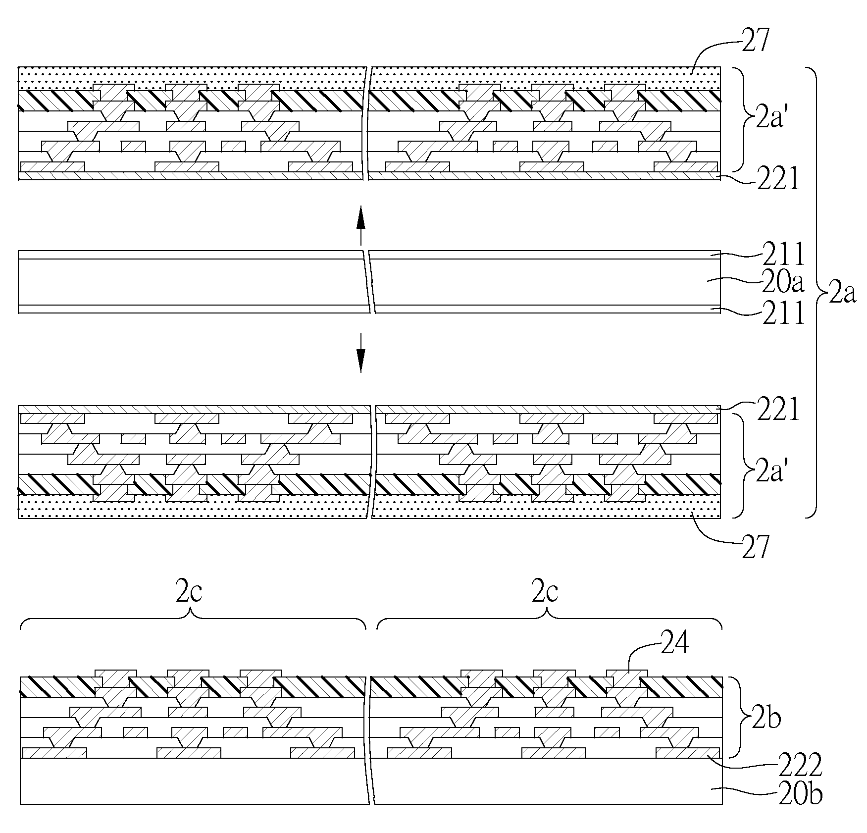
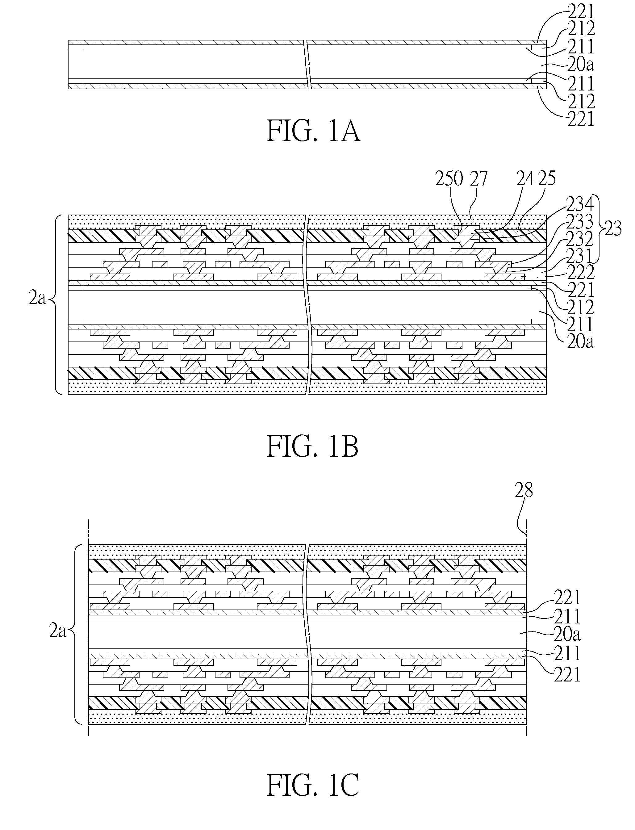
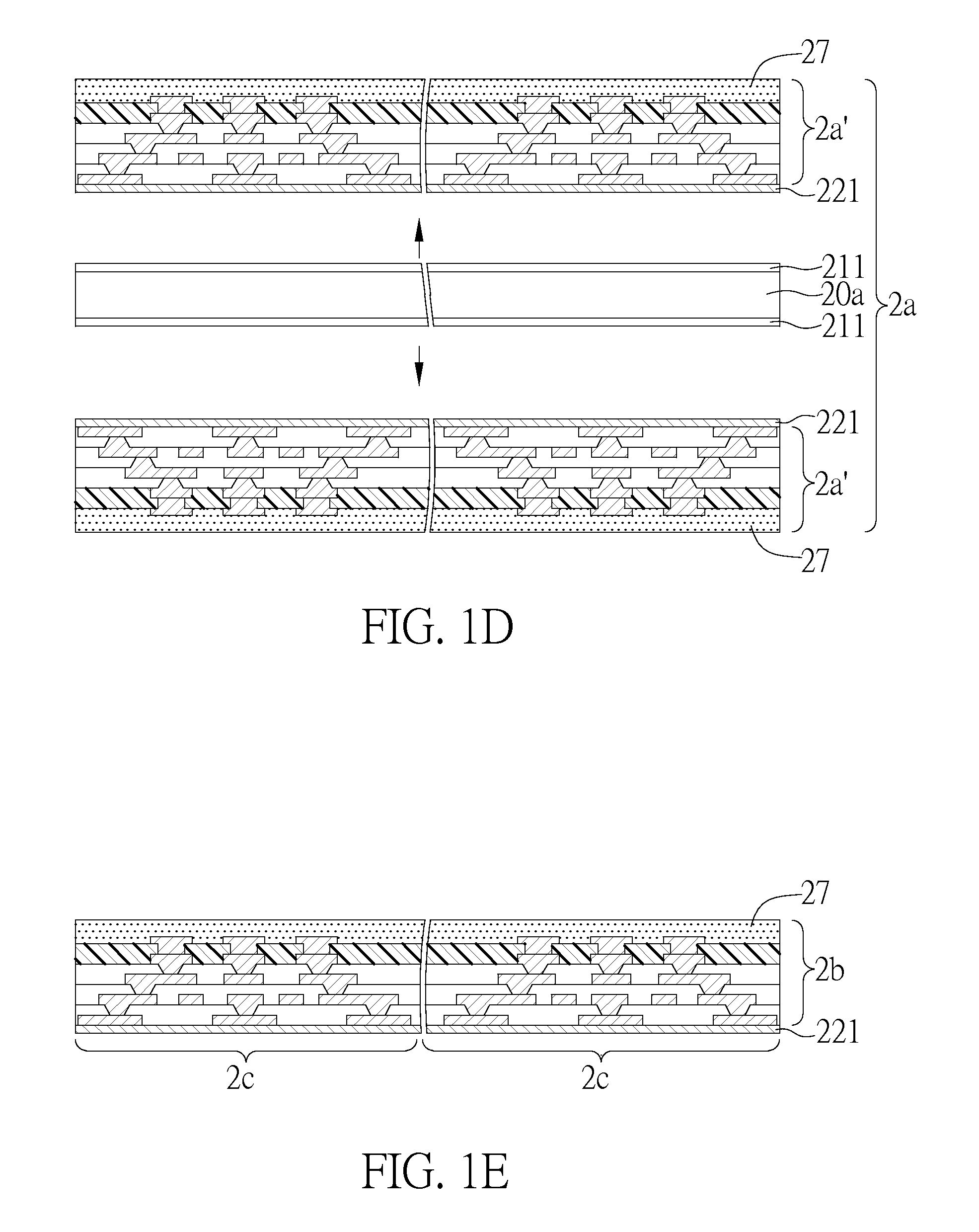
[0026]FIGS. 1A to 1H are cross-sectional views showing a fabrication method of a package structure according to a first embodiment of the present invention, wherein FIG. 1E′ is the top view of the structure of FIG. 1E.

[0027]Referring to FIG. 1A, a first carrier board 20a is provided, and a releasing layer 211 is formed on the two opposing surfaces of the first carrier board 20a such that the area of the releasing layer 211 is of an area less than the first carrier board 20a. An adhesive layer 212 is formed on the first carrier board 20a and along the periphery of the releasing layer 211, and a metal layer 221 is formed on the releasing layer 211 and the adhesive layer 212, wherein the releasing layer 211 is a releasing film, the metal layer 221 is made of copper and used as a seed layer in an electroplating process.

[0028]Referring to FIG. 1B, a plurality of conductive pads 222 and a built-up structure 23 are sequentially formed on the metal layer 221 on the two opposing surfaces of ...

second embodiment

[0034]FIGS. 2A to 2H are cross-sectional views showing a fabrication method of a package structure according to a second embodiment of the present invention.

[0035]Referring to FIG. 2A, a first carrier board 20a is provided, a releasing layer 211 is formed on the two opposing surfaces of the first carrier board 20a and has an area less than that of the first carrier board 20a, an adhesive layer 212 is formed on the first carrier board 20a around the releasing layer 211, and a metal layer 221 is formed on the releasing layer 211 and the adhesive layer 212, wherein the releasing layer 211 is a releasing film, and the metal layer 221 is made of copper and used as a seed layer in an electroplating process. Subsequently, a plurality of conductive pads 222 and a built-up structure 23 are sequentially formed on the metal layer 221 on the two opposing surfaces of the first carrier board 20a, wherein the built-up structure 23 comprises at least a dielectric layer 231, a wiring layer 233 forme...


PUM


Abstract

Provided is a fabrication method of a package structure, including cutting a full-panel packaging substrate into a plurality of packaging substrate blocks, each of which has a plurality of packaging substrate units; mounting and packaging a semiconductor chip on each of the packaging substrate units and securing and protecting the semiconductor chips with an encapsulating material, thereby forming a plurality of packaging substrate blocks with packaging substrate units; and cutting the packaging substrate blocks to separate the packaging substrate units from each other. In the fabrication process, the alignment error between packaging substrate units in each packaging substrate block can be reduced by cutting the packaging substrate into packaging substrate blocks of appropriate size, thereby increasing the yield, and also the packaging of the semiconductor chips can be performed at the same time on all packaging substrate units in each substrate block so as to integrate fabrication of substrates with the packaging of semiconductor chips to simplify fabrication steps, thus increasing the productivity and reducing fabrication costs.

Description

CROSS-REFERENCES TO RELATED APPLICATIONS[0001]This application claims under 35 U.S.C. §119(a) the benefit of Taiwanese Application No. 098129496 filed Sep. 2, 2009, the entire contents of which is incorporated herein by reference.BACKGROUND OF THE INVENTION[0002]1. Field of the Invention[0003]The present invention relates generally to fabrication methods of package structures, and more particularly, to a fabrication method of a package structure capable of increasing productivity and reducing fabrication costs.[0004]2. Description of Related Art[0005]In flip chip packaging technology, a semiconductor chip has a plurality of electrode pads formed on an active surface thereof, a substrate has a plurality of conductive pads formed on a surface thereof and corresponding in position to the electrode pads, and the electrode pads and the corresponding conductive pads are electrically connected by a plurality of solder bumps.[0006]Compared with conventional wire bonding technology that esta...

Claims


Application Information

Patent Timeline
Patent Type & Authority Patents(United States)
IPC IPC(8): H01L21/50
CPCH01L21/481H01L21/6835H01L24/16H01L24/81H01L24/97H01L2224/16225H01L23/49816H01L23/49822H01L2221/68318H01L2221/68345H01L2221/68381H01L2224/13099H01L2224/16227H01L2224/16235H01L2224/81193H01L2224/97H01L2924/01029H01L2924/01079H01L2924/15174H01L2924/15311H01L21/4857H01L2924/014H01L2924/01033H01L2924/01006H01L2924/01005H01L2224/81
Inventor HU, CHU-CHIN
Owner UNIMICRON TECH CORP
Learn More