Two part transformer core, transformer and method of manufacture

a transformer and two-part technology, applied in the field of power transformation, can solve the problems of transformer failure, thermal runaway, transformer failure, etc., and achieve the effects of less and/or lower cost materials, improved efficiency, and compact arrangemen

Inactive Publication Date: 2006-06-15
DELTA TRANSFORMERS +1
View PDF10 Cites 19 Cited by
  • Summary
  • Abstract
  • Description
  • Claims
  • Application Information

AI Technical Summary

Benefits of technology

[0014] It is a further object of the invention to provide a transformer with improved efficiency, and a more compact arrangement using less and / or lower cost materials, in comparison with standard known transformers.

Problems solved by technology

The producers of ‘soft magnetic materials’ for the transformer industry, have consequently, made it difficult to realize new transformer topologies.
A cooling mechanism is needed to dissipate the heat maintaining a thermal equilibrium of the transformer, as otherwise “thermal runaway” occurs and the transformer fails.
Thermal runaway occurs when the energy or power losses of the transformer produces more heat than can be dissipated by the transformer.
This is very wasteful in terms of winding wire material content since winding wire is expensive and can contribute to over half the total material content.
Also the exposure of the windings and core brings about external leakage of flux.
Furthermore, the thermal transfer between the copper winding and air is best when the winding is directly exposed to the air, but cannot exceed a certain thermal transfer rate.
In reality the minimum material content of transformers are not materialized because of the thermal dissipation requirements, and because the costs of materials, practical constraints on construction methods, etc.
However, toroidal transformers cannot be easily configured into 3-phase transformers where portions of the core can share and partially cancel magnetic flux vectors.
The technical challenge in designing transformers is only exacerbated with increase in power losses due to the winding current.
Furthermore, as cores get larger the ratio of surface area to volume of material decreases, thus the capacity to dissipate heat becomes more of a problem for a certain dissipation per cubic meter.
In high power transformers cores can be large enough to cause very high temperature rises inside the core causing dimensional distortion and mechanical stresses that affect magnetic properties of the core.
Also, for very large transformers, the core heat affects the winding adjacent to the core requiring extra spacing to cool the core and winding.
This further decreases efficiency of the transformer, and increases material costs, noise and vibration of the transformer.

Method used


Image

  • Two part transformer core, transformer and method of manufacture
  • Two part transformer core, transformer and method of manufacture
  • Two part transformer core, transformer and method of manufacture

Examples


Embodiment Construction

[0028] The present invention provides a topology for a transformer, transformers and methods of designing and constructing a transformer to produce efficient transformers with significantly lower material costs, improved efficiency and improved thermal dissipation.

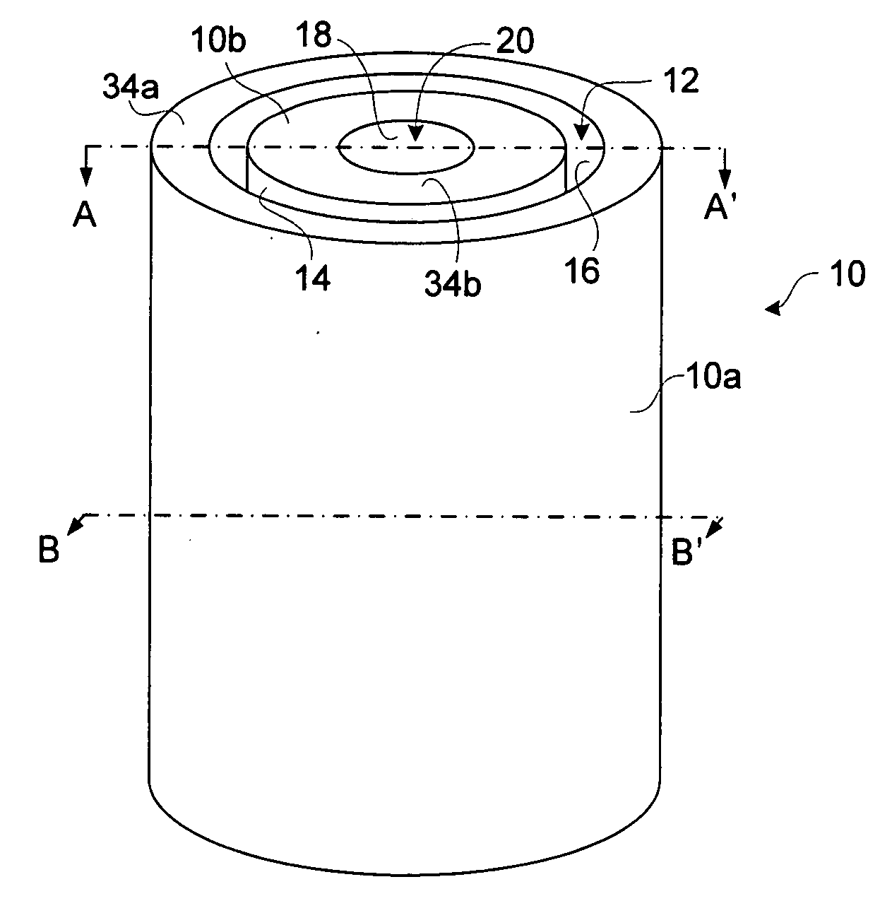
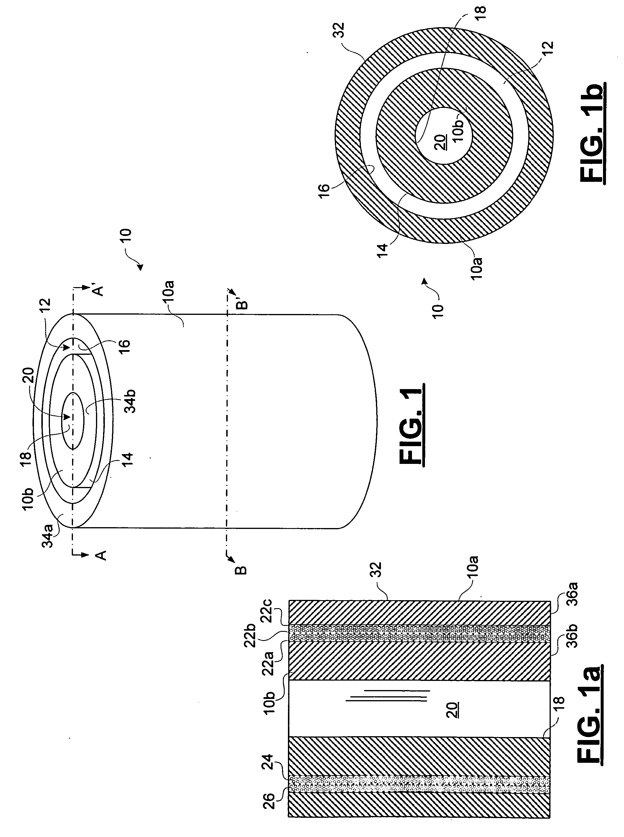
[0029]FIGS. 1, 1a and 1b schematically illustrate a transformer topology in accordance with an embodiment of the invention. The transformer topology shown includes a two-part core 10, consisting of a shell piece 10a and a toroidal piece 10b made of a magnetic material, such as magnetic steel. Both the shell piece 10a and the toroidal piece 10b are hollow cylindrical pieces, with an inner radius of the shell piece 10a being greater than the outer radius of the toroidal piece 10b, although it will be appreciated that other shapes of the shell piece 10a and toroidal piece 10b are equally possible if they permit the toroidal piece to be disposed concentrically within the shell piece 10b providing a space between the two. Beca...


PUM

PropertyMeasurementUnit
power frequencyaaaaaaaaaa
input currentaaaaaaaaaa

Abstract

A toroidal transformer core topology having improved thermal and electrical properties has a two part core, one part concentrically disposed within the other, with the windings wound between the two. Less expensive materials and less material can be used to construct the core. The core can be constructed using inexpensive and efficient methods.

Description

CROSS-REFERENCE TO RELATED APPLICATIONS [0001] This is the first application filed for the present invention. MICROFICHE APPENDIX [0002] Not Applicable. TECHNICAL FIELD [0003] The present invention relates in general to power transformation, and in particular to a two part transformer core and transformers made with such a core. BACKGROUND OF THE INVENTION [0004] Transformers for distribution and power have improved greatly in the last decade due to improved materials, and sophisticated design tools for optimizing performance, cost and size. Recent energy saving legislation in North America commonly known as “Energy Star” in the USA and “C 802” in Canada drive the issues of cost and energy savings, which has spawned significant developments in the art of transformer design. Manufactures are faced with an ever-increasing competitive market and stringent power efficiency requirements for their products. [0005] A large part of transformer costs is based on material, such as the copper / ...

Claims


Application Information

Patent Timeline
Patent Type & Authority Applications(United States)
IPC IPC(8): H01F27/28
CPCH01F3/10H01F27/085Y10T29/4902H01F30/12H01F41/0213H01F27/25
Inventor PIASKOWSKI, ANDREW D.
Owner DELTA TRANSFORMERS
Why Eureka
Try Eureka