Method for locating a backscatter-based transponder

a backscatter-based transponder and transponder technology, applied in the field of backscatter-based transponders, can solve the problems of interference spectrum, change in the amplitude of the received carrier signal, unidirectional or bidirectional wireless transmission of data, etc., and achieve the effect of simplifying evaluation

Inactive Publication Date: 2006-06-15
ATMEL CORP
View PDF6 Cites 26 Cited by
  • Summary
  • Abstract
  • Description
  • Claims
  • Application Information

AI Technical Summary

Benefits of technology

[0029] In a further embodiment, the locating signal can be generated by modulating the carrier signal transmitted from the base station with a subcarrier. The modulation of the carrier signal with a subcarrier is described, for example, in the textbook by Klaus Finkenzeller, RFID-Handbuch, 3rd edition, HANSER, 2002, see especially Chapter 3.2.1.2.2, (load modulation with subcarriers). Modulation of the carrier signal with a subcarrier permits simplified evaluation of the backscattered signal in the base station, since the backscattered signal, which is significantly weaker in comparison to the carrier signal, is shifted in the frequency range into sidebands, and thus can be separated from the carrier signal in the base station by appropriate filters.
[0030] In a further embodiment of the invention, a memory internal to the transponder can contain one or more parameters for setting the locating signal, in particular a frequency. The parameters can also be transferred to the transponder through a command, for example, in the form of command parameters. In the case that a selection process is needed, t...

Problems solved by technology

In these systems, unidirectional or bidirectional wireless transmission of data takes place between one or more base stations, or readers, and one or more transponders.
This so-called polling causes an interference spectrum.
Thereby, the self caused fluctuations of the input amplitude of the received carrier signal that are caused by the transponder itself, an that arise during the generation of the locating signal through amplitude modulation and backscatteri...

Method used


Image

  • Method for locating a backscatter-based transponder
  • Method for locating a backscatter-based transponder
  • Method for locating a backscatter-based transponder

Examples


Embodiment Construction

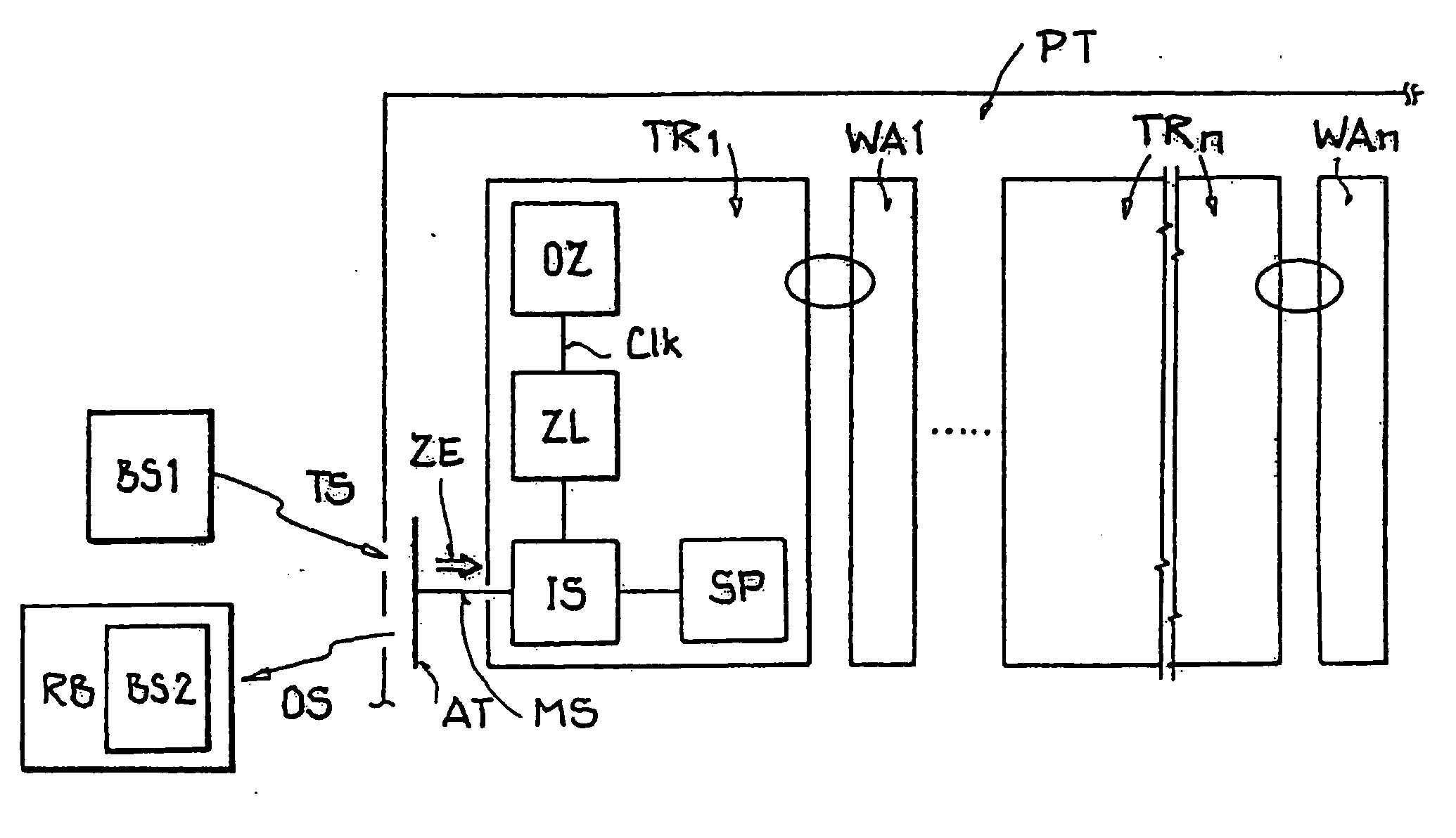
[0039]FIG. 1 shows a transponder-based pick-and-place application, which may be used in an inventory management system, for example. The application shown includes a first base station BS1, a robot RB that includes a second base station BS2, and a pallet PT upon which are arranged multiple goods WA1 through WAn, each of which is marked with its associated passive backscatter-based transponder TR1 through TRn.

[0040] The transponders TR1 through TRn each include a memory SP, an oscillator OZ, a counter ZL, an impedance control device IS, and an antenna AT.

[0041] The base station BS1 emits a carrier signal TS in the UHF range that serves to supply the transponders TR1 through TRn and is backscattered as a locating signal OS with phase modulation as soon as the transponder is in a transmit / receive range of the base station BS1.

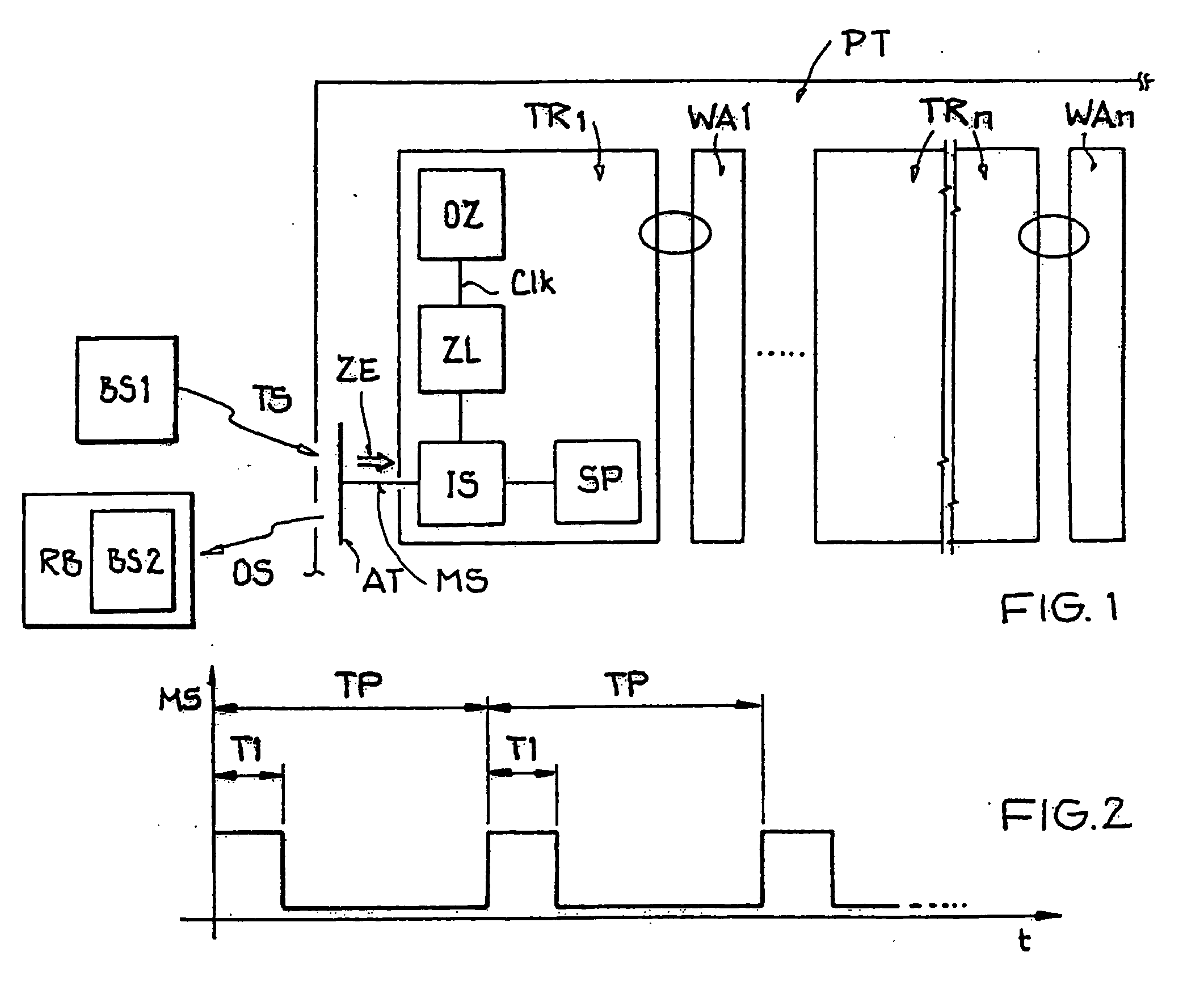
[0042]FIG. 2 shows a diagram of a time behavior of a modulation signal MS generated in the applicable transponder TR1 to TRn for modulating the carrier signal ...


PUM


Abstract

A method and apparatus for locating a transponder is provided. A carrier signal is transmitted by a base station and a transponder transmits a locating signal that is generated through phase modulation and backscattering of the carrier signal sent by the base station when the transponder is within a transmission range of the base station, whereby the transponder is located on the basis of the locating signal.

Description

[0001] This nonprovisional application claims priority under 35 U.S.C. § 119(a) on German Patent Application No. DE 102004062365.1, which was filed in Germany on Dec. 13, 2004, and which is herein incorporated by reference. BACKGROUND OF THE INVENTION [0002] 1. Field of the Invention [0003] The present invention relates to a method for locating a backscatter-based transponder. [0004] 2. Description of the Background Art [0005] Transponders are used in radio frequency identification (RFID) systems. In these systems, unidirectional or bidirectional wireless transmission of data takes place between one or more base stations, or readers, and one or more transponders. Sensors, for example for temperature measurement, may also be integrated in the transponders. Such transponders are also referred to as remote sensors. [0006] The transponders and their transmitting and receiving devices customarily do not have an active transmitter for data transmission to the base station. Such non-active...

Claims


Application Information

Patent Timeline
IPC IPC(8): H04Q5/22
CPCG06K7/0008G06K19/0723H04Q5/22
Inventor FISCHER, MARTINFRIEDRICH, ULRICHMASUCH, JENSPANGELS, MICHAELZIEBERTZ, DIRK
Owner ATMEL CORP
Why Eureka
Try Eureka