Distributed exciter in phased array

a phased array and exciter technology, applied in the field of antennas, can solve the problems of increasing the complexity of the system implementation with conventional phased array architecture, reducing the degree of modularity and interchangeability of the system, and increasing the complexity of the feed network and support electronics of this type of jammer

Inactive Publication Date: 2006-06-15
BAE SYST INFORMATION & ELECTRONICS SYST INTERGRATION INC
View PDF21 Cites 45 Cited by
  • Summary
  • Abstract
  • Description
  • Claims
  • Application Information

AI Technical Summary

Benefits of technology

[0011] The system may further include an amplifier that is adapted to amplify the signals converted to transmission frequencies prior to transmission. Note that the phased antenna array can include multiple antenna elements. In one such particular case, there is an identical multi-signal generator and RF converter set associated with each element. Each identical set may also include an amplifier. Likewise, there can be an identical multi-signal generator, RF converter, and amplifier set associated with each of the antenna array bands. Thus, a high degree of modularity and interchangeability is provided.

Problems solved by technology

However, the feed network and support electronics for this type of jammer is complex and contains a large number of individual hardware RF elements including multiple amplitude adjust modules (coarse and fine), time delay modules, phase shift modules, and directional couplers.
Adding this capability further increases the system complexity by nearly the number of signal beams.
As such, the system implementation with conventional phased array architectures approaches a practical limit that precludes extending the architecture to more than a hand full of radio wave signals.
This leads to a design that places many demands on the RF elements of the system when beam steering and signal polarization control is required.
Unfortunately, for large phased arrays with large steering angles, the TTD phase shifter nears the limit of its own technology and must be controlled and calibrated with an internal microprocessor and factory calibration table.
The additional requirement of polarization control and amplitude leveling adds even further to the system complexity in the area of RF hardware.
In short, conventional phased array techniques and beam forming architectures are relatively large, require more components, use a significant amount of power, and provide limited flexibility.

Method used


Image

  • Distributed exciter in phased array
  • Distributed exciter in phased array
  • Distributed exciter in phased array

Examples


Embodiment Construction

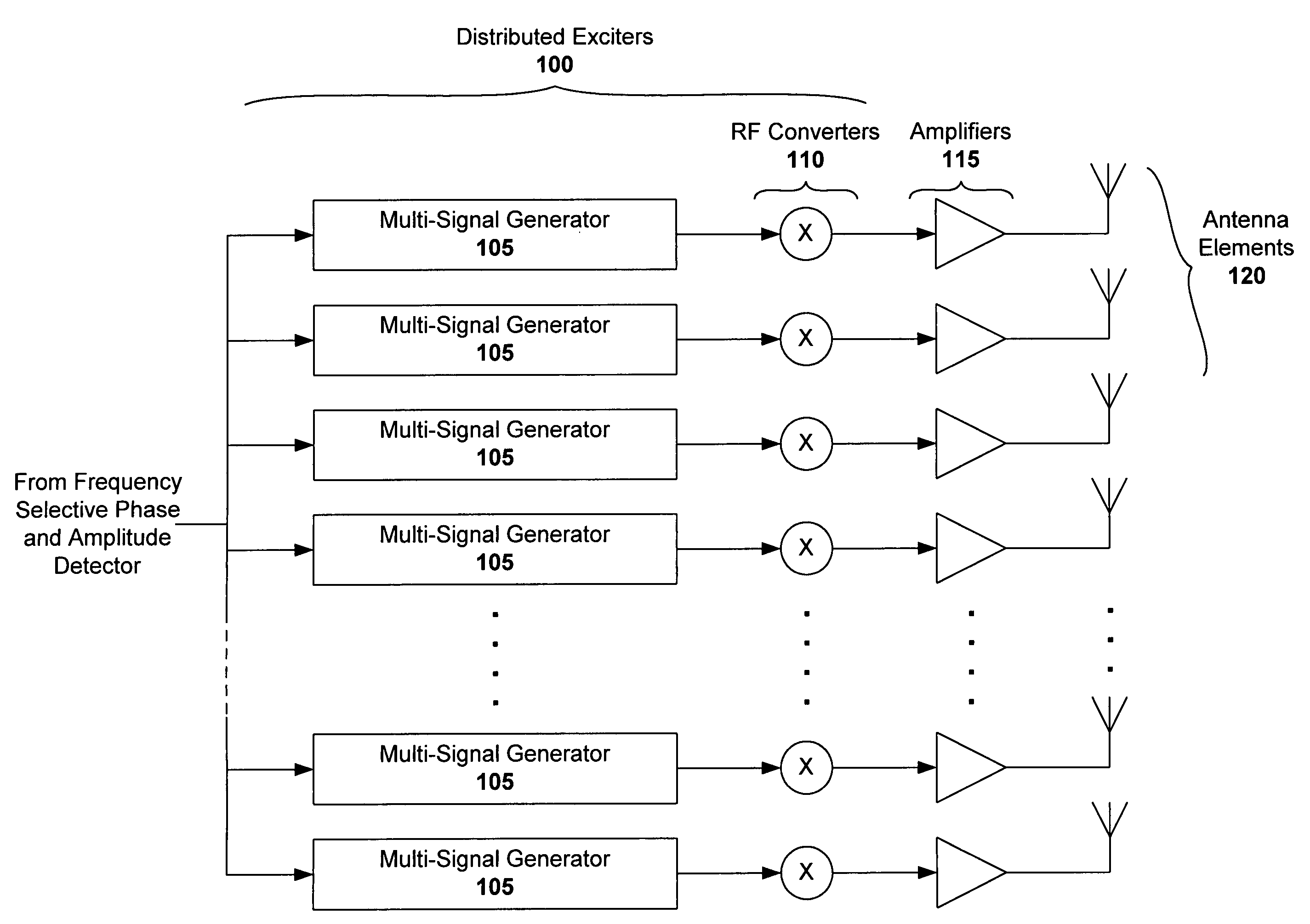
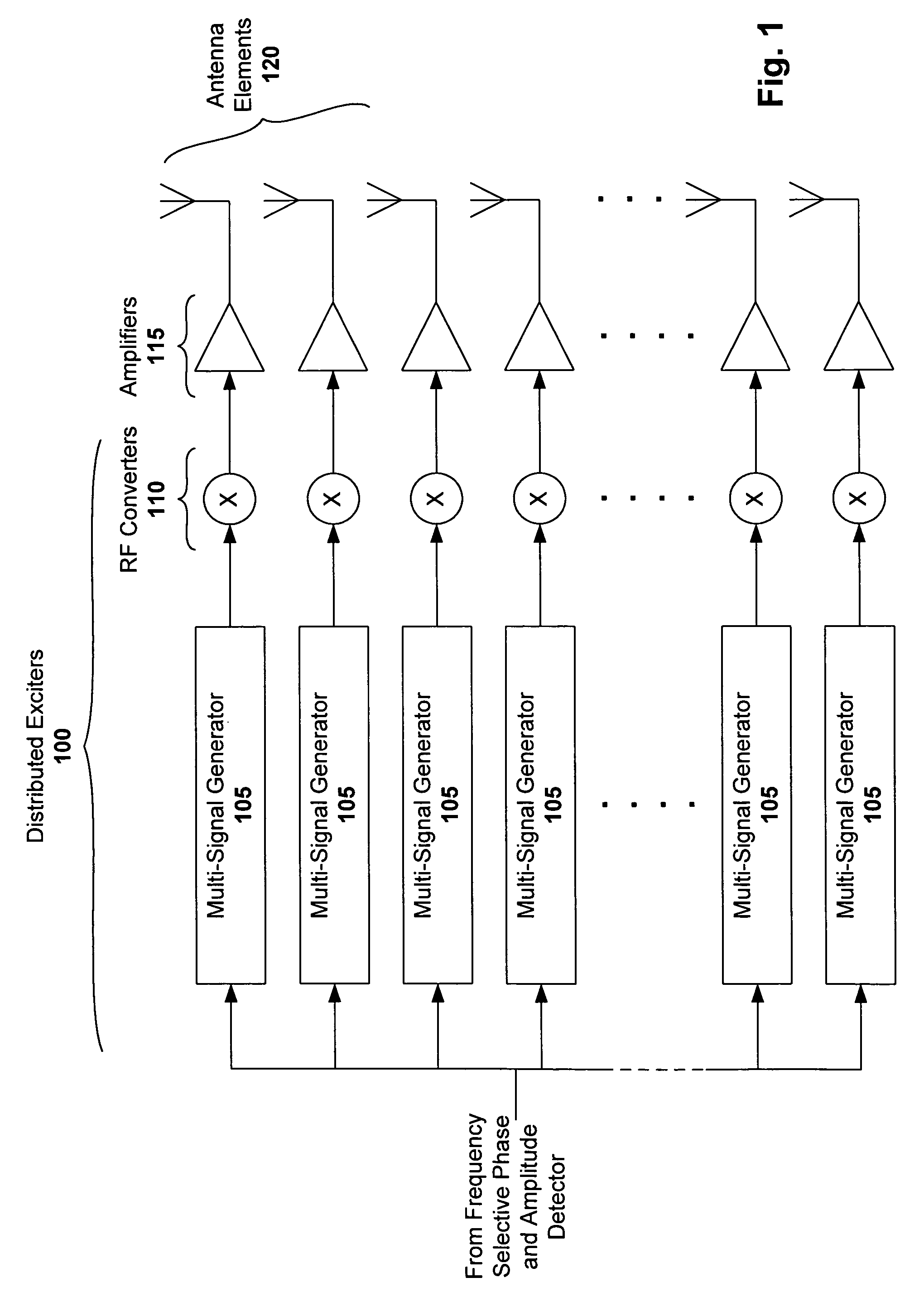
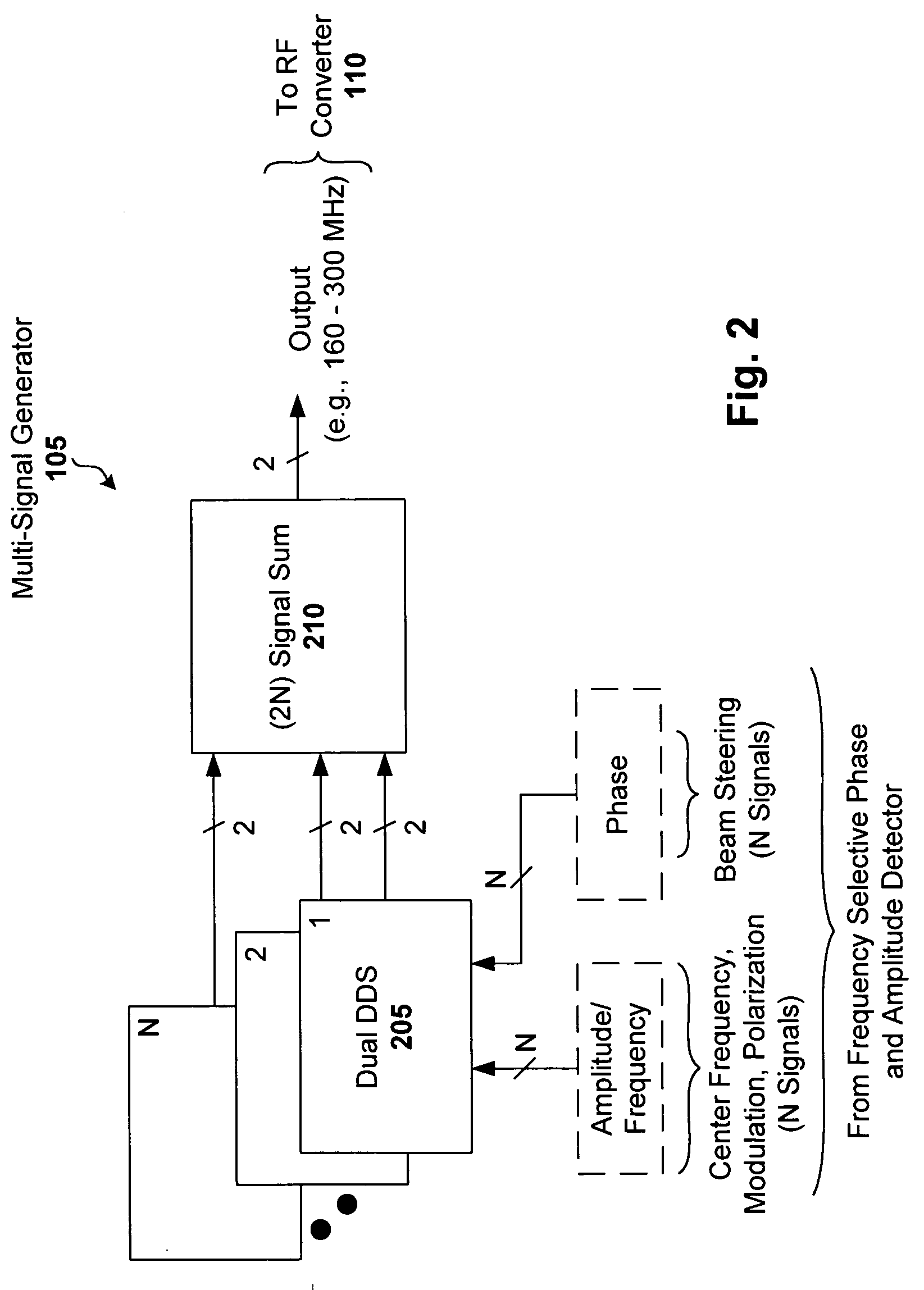
[0016] Rather than extend conventional phased array beam steering and polarization technology to meet additional performance demands, an embodiment of the present invention is configured to simplify the RF hardware to the maximum degree possible by moving all of the beam steering, delay compensation (TTD-related), phase matching, amplitude leveling and polarization control functions to a highly modular distributed exciter with coordinated and precise phase and amplitude control.

[0017] Here, the phase characteristics of the array, its amplifiers and the RF distributing hardware can be characterized (as opposed to matched) for each element RF path and the results reduced to a digital phase compensation table with modulo 360 degree output (e.g., included in a direct digital frequency synthesizer chip). Likewise the requirements for beam steering verse frequency for each array element can also be pre-calculated to result in a phase offset for steering. Signal polarization control is ac...


PUM


Abstract

A wideband multi-signal distributed exciter system for use with a phased antenna array is disclosed. The system includes a multi-signal generator that is configured with a dual direct digital frequency synthesizer (DDS) core, and is capable of generating multi-polarization signals over a given frequency range (e.g., 50 to 500 MHz) for each of N signals associated with a corresponding antenna element. An RF converter is adapted to receive multi-polarization signals from the multi-signal generator, and to convert those signals to a transmission frequency (e.g., 100 MHz to 10 GHz). A 2N signal summing module can be used to receive multi-polarization signals from each of the N dual DDS functions, and to generate an overall multi-polarization output signal that is provided for RF conversion. An identical set of multi-signal generator and RF converter modules can be associated with each element, thereby providing a high degree of modularity and interchangeability.

Description

FIELD OF THE INVENTION [0001] The invention relates to antennas, and more particularly, to phased array techniques and architectures that enable modularity and enhanced performance, including the ability to independently steer individual beams for each signal. BACKGROUND OF THE INVENTION [0002] A phased array is a group of antennas in which the relative phases of respective signals feeding the antennas are varied so that radiation patterns of the array are coordinated so that the radio wave signals are reinforced in certain directions and suppressed in others. The relative amplitudes of the signals, as well as the constructive and destructive interference effects among the signals radiated by the individual antennas, determine the effective radiation pattern of the array. [0003] A phased array may be used to point a fixed radiation pattern, or to scan rapidly in azimuth or elevation. Transmitters utilizing phased array techniques have been implemented successfully for many years. Co...

Claims


Application Information

Patent Timeline
Patent Type & Authority Applications(United States)
IPC IPC(8): H01Q3/26H04B7/10
CPCH01Q3/26H01Q21/0006
Inventor GREELEY, JOHN S.
Owner BAE SYST INFORMATION & ELECTRONICS SYST INTERGRATION INC
Why Eureka
Try Eureka