Video processing device

a video processing and video technology, applied in the field of video processing devices, can solve the problems of increasing the error rate of digital video information, unable to correct the error rate of audio information, and unable to achieve the effect of high error ra

Inactive Publication Date: 2006-06-15
HITACHI LTD
View PDF20 Cites 30 Cited by
  • Summary
  • Abstract
  • Description
  • Claims
  • Application Information

AI Technical Summary

Benefits of technology

[0010] In view of the problems described above, it is an object of the invention to provide an video processing device which can obtain an appropriate video signal (a less error rate) even when input digital video information has a high error rate.
[0014] When both of a digital video and audio signal and an analog video and audio signal are receivable, the analog video and audio signal may be selected if the digital audio signal has a high error rate. Besides, when the digital video signal is not being received, the analog signal may be selected, and when the analog signal is not being received, the digital video signal may be selected. Furthermore, when the reception circuit for receiving the digital video signal is receiving a signal indicating a still image (for example, image of solid black, solid white, etc.) having a single color or single brightness, an analog video signal may be selected. An energy-saving effect can be expected by lowering or suspending the supply of power to a non-selected circuit block.

Problems solved by technology

The digital video information tends to have an increased error rate because of a high transmission rate, a long cable being connected, or the like.
But, when a transmission distance is short, for example, between the STB and the display device, an error in audio information is inevitably corrected, but an error in video information is not corrected because of a cost problem.
In practice, it is possible that the occurrence of an error becomes a problem depending on a use environment, and some means are demanded in place of the error correction.

Method used


Image

  • Video processing device
  • Video processing device
  • Video processing device

Examples


first embodiment

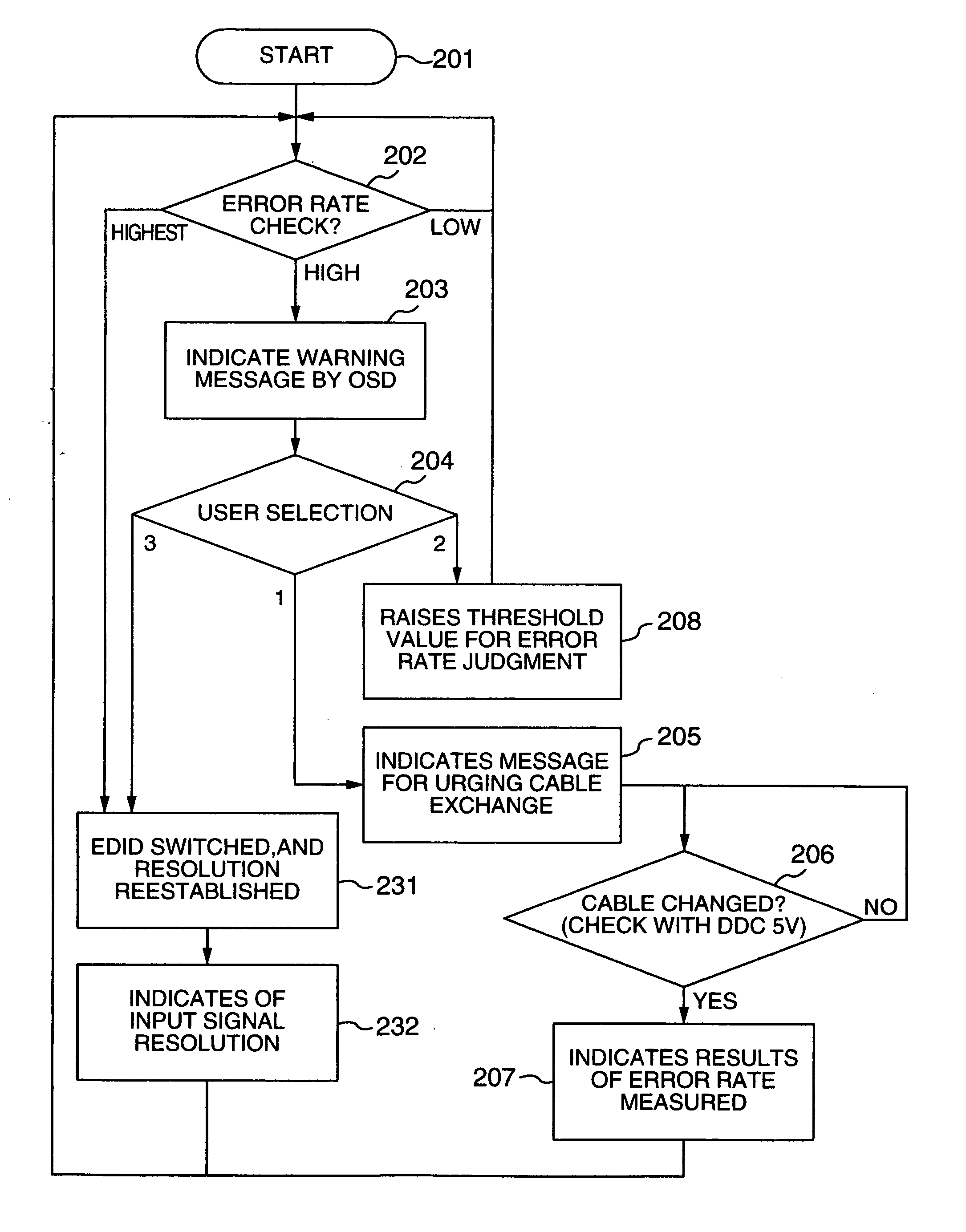
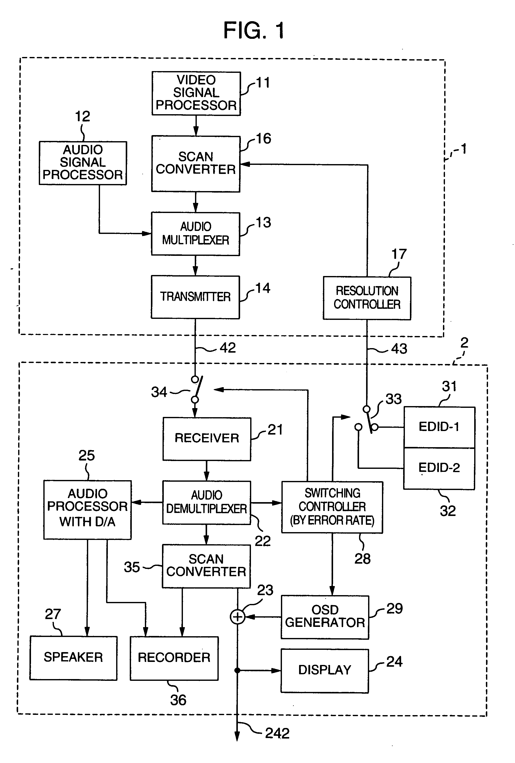
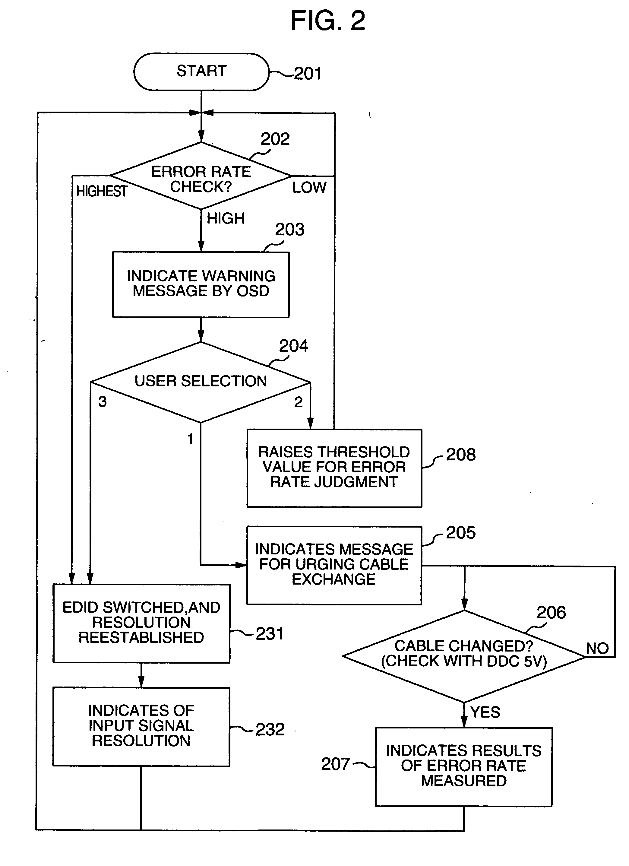
[0028] An operation for the above processing will be described with reference to FIG. 1 with special emphasis on the items mentioned above. FIG. 1 is a block diagram showing the invention and it is provided with a signal generating device 1 such as an STB and a video processing device 2. Here, the video processing device 2 will be described referring to a display device such as a television receiver. They are mutually connected through two interfaces (cables or the like) 42, 43. In this embodiment, the signal generating device 1 and the video processing device 2 are connected through the two interfaces, but they may be connected through a single interface when such communications functions can be made by a single interface.

[0029] First, details of the signal generating device 1 will be described. A digital video, signal is generated from a video signal source 11 of the signal generating device 1, and a digital audio signal is generated from an audio signal processor 12. When the sig...

second embodiment

[0052] Then, the invention will be described with reference to the block diagram of FIG. 5. Here, an interface of video information between the signal generating device 1 and the display device 2 is performed by two systems of digital and analog, and a preferable one (in terms of image quality) is selected for displaying.

[0053] In FIG. 5, like reference numerals are used to indicate like components as those shown in FIG. 1. Components related to the transmission of an audio signal are omitted. In the signal generating device 1, the video signal generated by the digital video signal source 11 is divided into two systems. One of the divided signals is supplied to the video processing device 2 which is a display device in a digital form via a first scan converter 161, a digital transmitter 142 and then the interface 42. The other is supplied to the video processing device 2 through an interface 41 as an analog form video signal after passing through a second scan converter 162 and a DA...

third embodiment

[0062] Then, the invention will be described with reference to the block diagram of FIG. 6. Here, when two systems of digital audio and analog audio are being sent, one with desirable sound quality is selected and reproduced.

[0063] In FIG. 6, like reference numerals are used for like components as those shown in FIG. 1. In the signal generating device 1, the digital audio signal generated by the digital audio signal processor 12 is divided into two systems, and one of them is passed through the audio multiplexer 13, where the digital sound is superimposed on the digital video signal, and the digital transmitter 14 so to be supplied to the video processing device 2, which is a display device, through the interface 42. The other is passed through the DAC so to be changed to an analog audio signal and supplied to the video processing device 2 through the interface 44.

[0064] In the display device 2, an audio switching controller 282 decides which of the analog audio or the digital audi...


PUM


Abstract

A video processing device includes a control circuit for detecting a physical quantity related to a size of noise contained in the input video signal, and an OSD (On Screen Display) circuit for providing a user with a warning screen when the physical quantity detected by the control circuit is larger than a prescribed value, obtaining an appropriate video signal even when a digital video signal has poor quality.

Description

RELATED APPLICATION [0001] This application is a continuation of U.S. application Ser. No. 10 / 109,041, filed on Mar. 29, 2002, which in turn claims the benefit of Japanese Application No. 2001-344013, filed on Nov. 9, 2001, and Japanese Application No. 2001-393106, filed on Dec. 26, 2001, the disclosures of which Applications are incorporated by reference herein.BACKGROUND OF THE INVENTION [0002] The present invention relates to a video processing device capable of adapting digital video and audio signals in television broadcasting, movie software and other package media. [0003] The digitalization of the video and the audio signal is advancing in these days. Accordingly, a broadcast receiving device (hereafter called as STB; set-top-box) which receives television signals, a digital recording player, an HD (High Definition) television receiver and other display devices have become possible to correspond to the digital video signals and the audio signals. [0004] As is well known, info...

Claims


Application Information

Patent Timeline
Patent Type & Authority Applications(United States)
IPC IPC(8): H04N5/44H04N5/50H04N5/445H04N17/00H04N21/485
CPCH04N5/44513H04N17/004H04N21/485H04N21/8106H04N21/44209H04N21/4436H04N21/4882H04N21/43632H04N21/47
Inventor YOSHIZAWA, KAZUHIKOKABUTO, NOBUAKIYOSHIOKA, ATSUSHI
Owner HITACHI LTD
Why Eureka
Try Eureka