Optical element, method of manufacturing same, and optical apparatus using optical element

Inactive Publication Date: 2006-06-15
CANON KK
View PDF12 Cites 12 Cited by
  • Summary
  • Abstract
  • Description
  • Claims
  • Application Information

AI Technical Summary

Benefits of technology

[0011] Thus, according to the present invention, even if the pitch of a grating is rough,

Problems solved by technology

The former is poor in productivity, and the latter is high in price and is also high in maintenance cost.
Also, when a visible light range is taken into

Method used


Image

  • Optical element, method of manufacturing same, and optical apparatus using optical element
  • Optical element, method of manufacturing same, and optical apparatus using optical element
  • Optical element, method of manufacturing same, and optical apparatus using optical element

Examples


embodiment 1

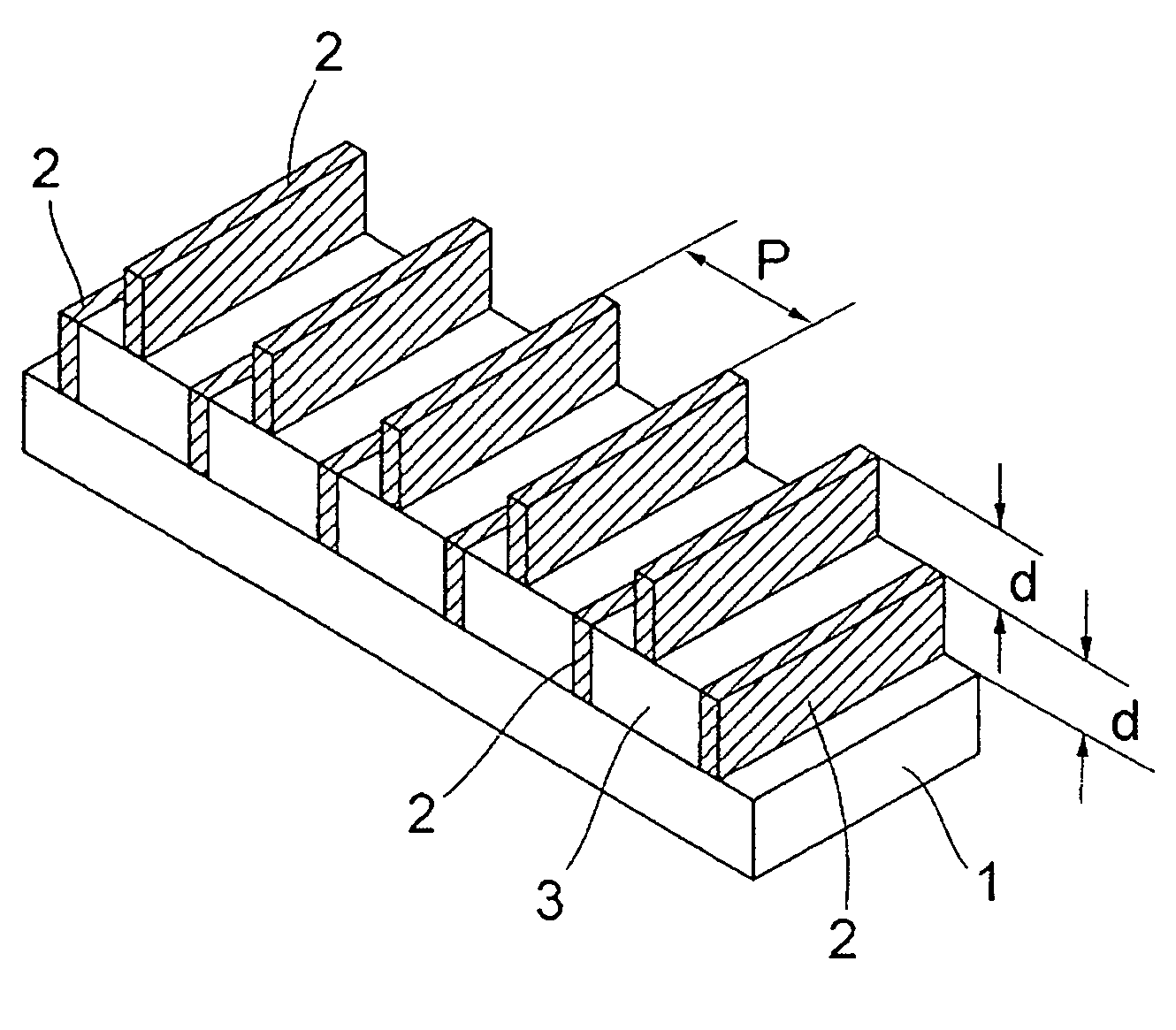
[0022]FIG. 1 shows the construction of a fine optical element according to Embodiment 1.

[0023] Grating portions 2 made of a metal are arranged as a first layer at regular intervals on a substrate 1, a filling material 3 fills the space between adjacent ones of the grating portions 2.

[0024] Also, as a second layer, only grating portions 2 are likewise arranged at regular intervals on the filling material 3.

[0025] When the pitch P of the grating portions 2 of a height d on the substrate 1 is selected to a value smaller than the wavelength λ of light used, the grating portions 2 function as deflecting plates.

[0026] When the pitch P of the grating portions 2 is sufficiently smaller than the wavelength λ, the function as the deflecting plates becomes best. However, it is still difficult by the actual machining technique.

[0027] So, by stacking a structure comprising grating portions 2 of a great pitch P, nearly the best performance is obtained.

[0028] In FIG. 1, the grating portions ...

embodiment 2

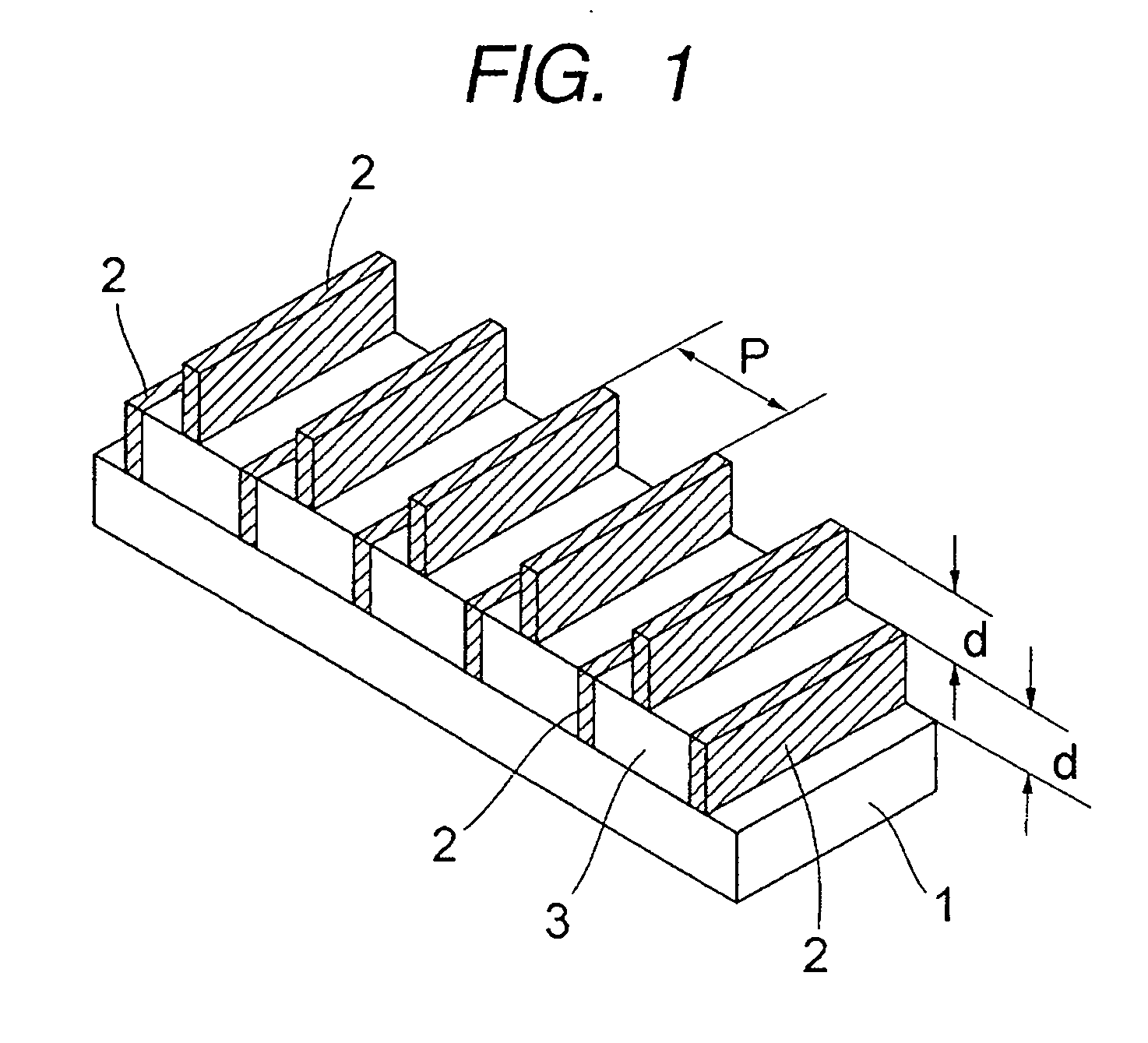
[0035]FIG. 3 shows the construction of an optical element according to Embodiment 2, and this construction is one in which two transparent substrates 1 to which grating portions 2 are fixed at regular intervals are fixed with the grating portions 2 fixed in opposed relationship with one another.

[0036] The principle of this Embodiment 2 is basically the same as that of Embodiment 1. Also, unlike Embodiment 1, the space between adjacent ones of the grating portions 2 as the first layer is filled with air which is small in refractive index, to thereby improve the quenching ratio γ.

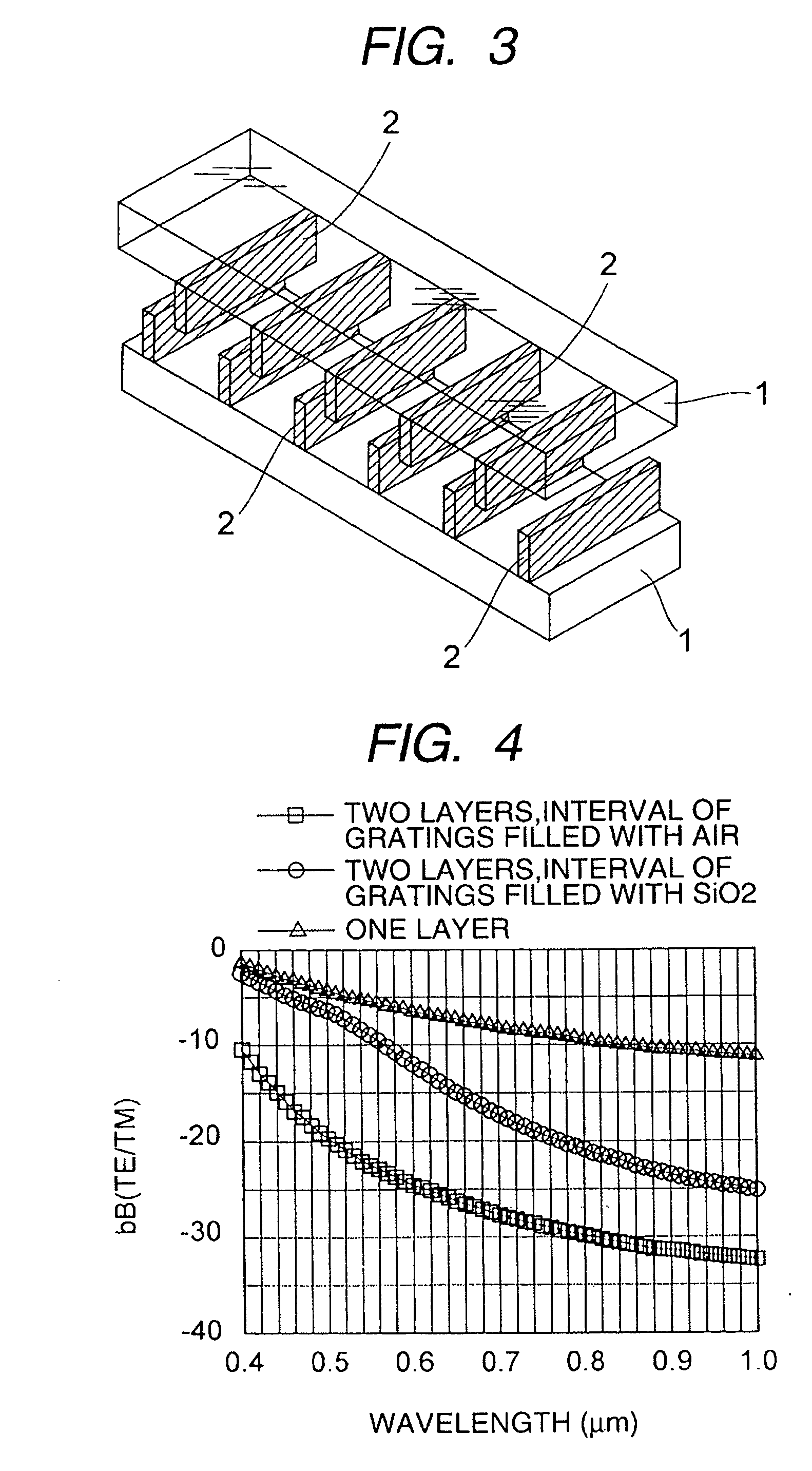
[0037] If here, the pitch P of the grating portions 2 is 0.26 μm, and the height d of the grating portions 2 is 0.15 μm, and a feeling factor f is 0.15, such characteristic of the quenching ratio γ as shown in FIG. 4 is obtained as the result of the simulation of RCWA.

[0038] In FIG. 4, points indicated by triangles represent the characteristic of the quenching ratio γ of a conventional grid wire deflecting...

embodiment 3

[0044]FIG. 5 shows the construction of an optical element according to Embodiment 3, in which on a substrate 1, there are arranged at regular intervals wall portions 4 provided with grating portions 2 on the uppermost portions thereof and having three kinds of heights.

[0045] Supporting portions 5 supporting the grating portions 2 are made of SiO2.

[0046] Also, the wall portions 4 having three different heights are arranged in the order of the heights, and combinations of three wall portions 4 repeatedly arranged.

[0047] The principle of this Embodiment 3 is also basically the same as that of Embodiment 1. The other portions than the SiO2 layers providing the supporting portions 5 under the grating portions 2 as the upper layer are air and therefore, the actual average refractive index becomes smaller than the refractive index of SiO2. Therefore, the quenching ratio γ of the stacked structures is improved.

[0048] Here, the pitch P of the grating portions 2 is 0.26 μm, the height d o...


PUM


Abstract

Grating portions made of a metal are arranged as a first layer at regular intervals on a substrate, and a filling material fills the space between adjacent ones of the grating portions. Also, as a second layer, only grating portions are likewise arranged at regular intervals on the filling material. Structures each comprising grating portions of a great pitch P are stacked one upon the other to thereby cause them to function as a deflecting plate having a small apparent pitch.

Description

BACKGROUND OF THE INVENTION [0001] 1. Field of the Invention [0002] This invention relates to an optical element for use in an optical apparatus for spectroscopy, optical measurement, optical communication, etc., a method of manufacturing the same, and an optical apparatus using the optical element. [0003] 2. Related Background Art [0004] The range of wavelength used in optical communication, optical measurement, etc. is sub μm to 2 μm. [0005] If to light in this range of wavelength, an attempt is made to make the pitch P of a grating into 1 / 10, the pitch P must be made smaller than 0.2 μm, and apparatuses which can made it are restricted to EB and a semiconductor exposing apparatus of the newest type ArF. [0006] The former is poor in productivity, and the latter is high in price and is also high in maintenance cost. Also, when a visible light range is taken into consideration, the grating is a grating having a pitch P of the order of 40 nm, and it is difficult to make it even by th...

Claims


Application Information

Patent Timeline
IPC IPC(8): H01S3/08
CPCG02B5/1809G02B5/1823G02B5/30G02B5/3058
Inventor KANEDA, YASUSHI
Owner CANON KK
Why Eureka
Try Eureka