
Method for producing carbon nanotubes using a dc non-transferred thermal plasma torch

a non-transferred thermal and plasma torch technology, applied in the direction of material nanotechnology, material nanotechnology, energy-based chemical/physical/physicochemical processes, etc., can solve the problem of limited scale up possibility for large yield, rapid movement of materials to tons/month requirements, and demand for cnt, etc. problem, to achieve the effect of adding to the scale up potential

Inactive Publication Date: 2006-06-15
MCGILL UNIV
View PDF25 Cites 21 Cited by
  • Summary
  • Abstract
  • Description
  • Claims
  • Application Information

AI Technical Summary

Benefits of technology

[0008] The method of this invention is based on DC plasma torch technology currently available and used for chemical synthesis and materials treatment at the multi-Megawatt power level. A carbon-containing gas is used as the source material for CNT generation. This gas is dissociated in the plasma environment to provide the atomic carbon for CNT growth. This is much more economical from the energy perspective than the solid carbon sublimation used in graphite arc and laser methods, and also adds to the scale up potential through the volumetric increase of gas treated at large power. An increase in process power translates into an increased amount of the carbon feed gas that is treated and transformed into CNT per unit time.

Problems solved by technology

State of the art techniques that are used presently for commercial production of carbon nanotubes show limitations in scale up possibility for large yields of fullerenes and CNT production, while the demand for CNT in emerging applications, for example in the field of materials is rapidly moving to the tons / month requirements.
Techniques such as the graphite arc methods that presently supply the carbon nanotube market (see U.S. Pat. Nos. 5,227,038; 5,482,601; 6,451,175 B1; 6,455,021; 6,063,243; and 5,753,088) are showing decreasing yields to nil as the arc power is increased, and poor energy efficiency.
This results in difficult control of the carbon to metal vapor ratio, and no possibility of real time adjustments.

Method used


Image

  • Method for producing carbon nanotubes using a dc non-transferred thermal plasma torch
  • Method for producing carbon nanotubes using a dc non-transferred thermal plasma torch
  • Method for producing carbon nanotubes using a dc non-transferred thermal plasma torch

Examples


Embodiment Construction

BRIEF DESCRIPTION OF THE DRAWINGS

[0013] The accompanying drawings are used for purposes of illustrating the invention only and should not be used to construe the claims in a limiting fashion.

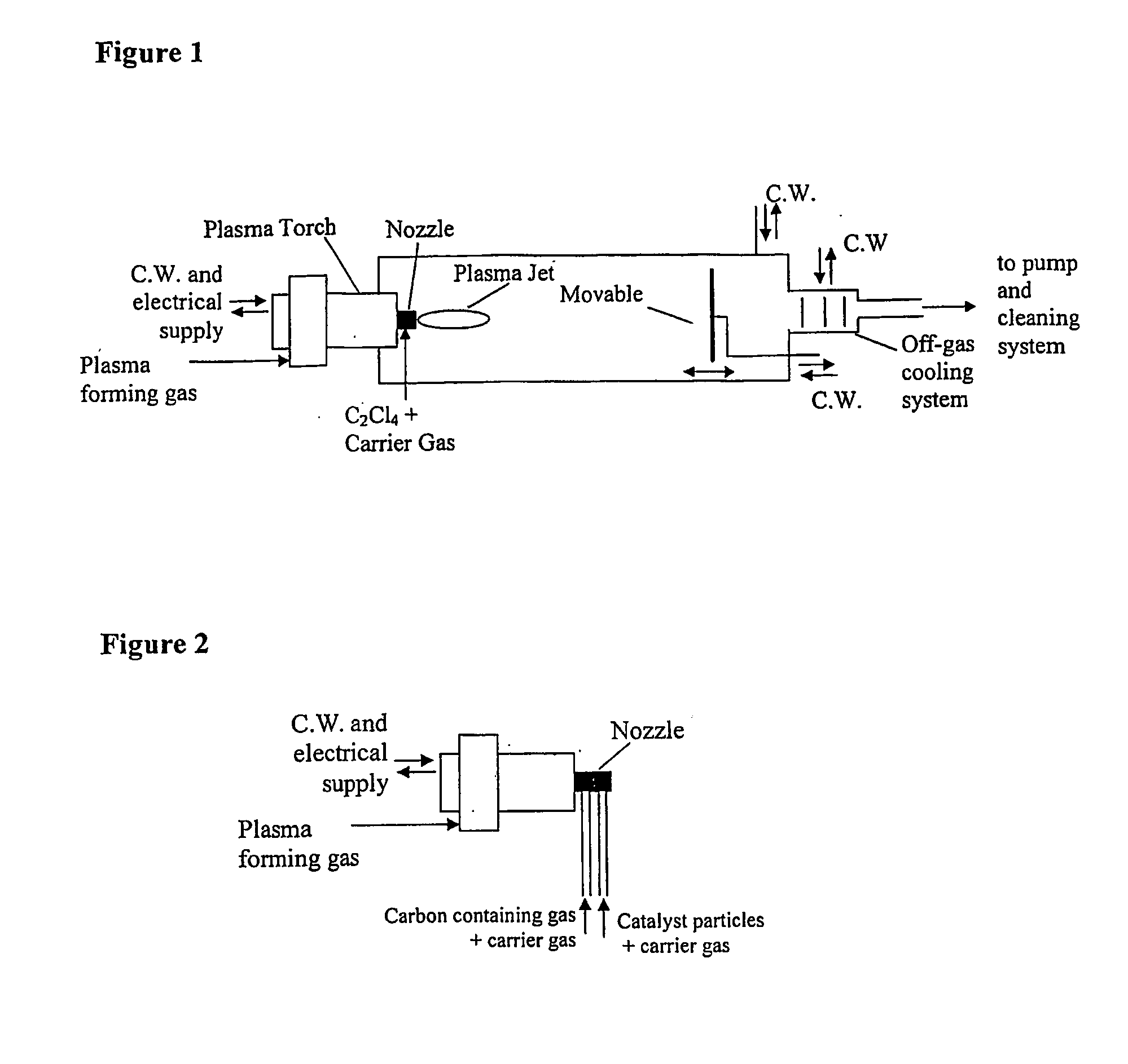
[0014]FIG. 1 is a schematic illustration of a high enthalpy plasma torch to which is attached a water-cooled nozzle for injection of a carbon-containing gas feed;

[0015]FIG. 2 is a schematic illustration of a plasma torch wherein a nozzle is shown that includes separate injection lines for carbon-containing gas and a carrier gas and for catalyst particles and a carrier gas;

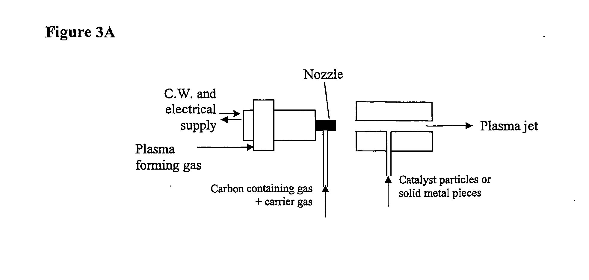
[0016]FIG. 3A is a schematic illustration of a portion of a plasma torch and a nozzle which provides for metal catalyst injection downstream of the plasma torch nozzle assembly;

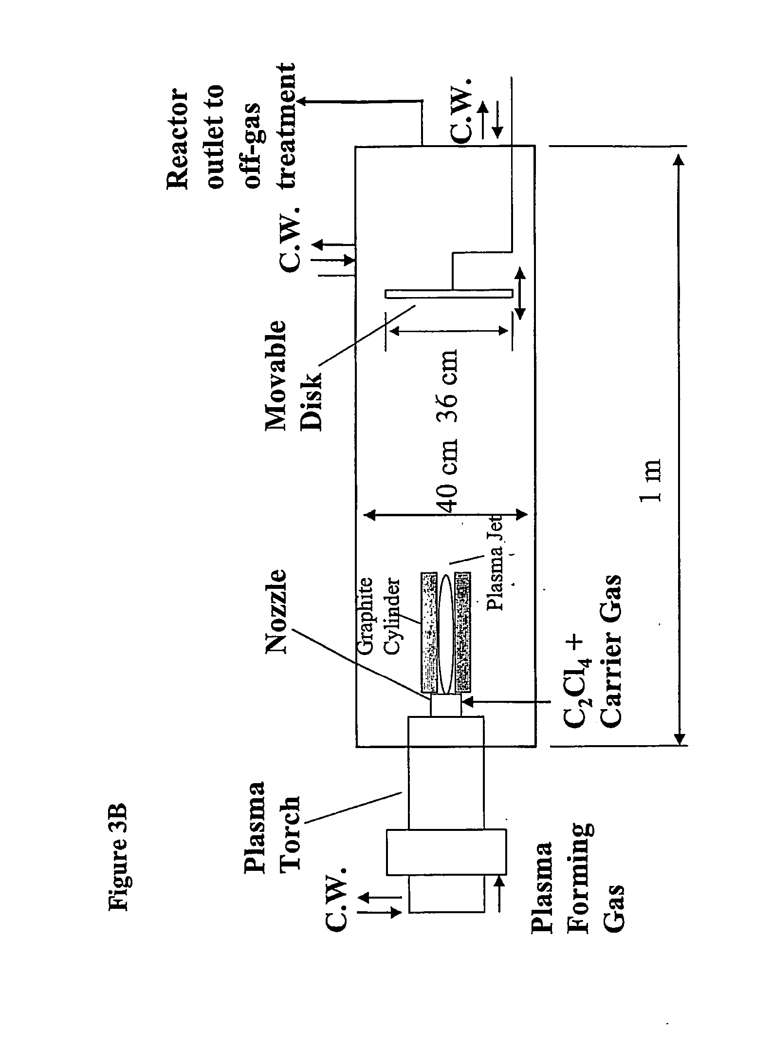
[0017]FIG. 3B is a schematic illustration of a high enthalpy plasma torch to which is attached a water-cooled nozzle for injection of a carbon-containing gas feed and wherein a hollow graphite cylinder is provided within the reactor;

[0018]FIG. 4 is ...


PUM


Abstract

The present invention provides a process for the manufacture of carbon nanostructures, the carbon nanostructures being selected from carbon nanotubes and carbon nano-onions. The method comprises the steps of injecting a carbon-containing gas into a plasma flame generated from a plasma forming gas to provide atomic carbon, which in the presence of in situ generated nanometer sized metal catalyst particles that act as nucleation points for growth of carbon nanostructures, produce the carbon nanostructures, and collecting the carbon nanostructures.

Description

FIELD OF THE INVENTION [0001] This invention relates to a method for producing carbon nanostructures such as carbon nanotubes and carbon nano-onions using a thermal plasma torch which involves in situ catalyst generation of nanometer sized metal catalyst particles. The method and apparatus provides a technique for the synthesis of carbon nanotubes (CNT) and carbon nano-onions with scale up possibilities to industrial (megawatt) levels. BACKGROUND OF THE INVENTION [0002] State of the art techniques that are used presently for commercial production of carbon nanotubes show limitations in scale up possibility for large yields of fullerenes and CNT production, while the demand for CNT in emerging applications, for example in the field of materials is rapidly moving to the tons / month requirements. [0003] Techniques such as the graphite arc methods that presently supply the carbon nanotube market (see U.S. Pat. Nos. 5,227,038; 5,482,601; 6,451,175 B1; 6,455,021; 6,063,243; and 5,753,088) ...

Claims


Application Information

Patent Timeline
IPC IPC(8): C01B31/02
CPCB82Y30/00B82Y40/00C01B31/0233C01B31/0293Y10S977/742Y10S977/842Y10S977/844
Inventor HARBEC, DAVIDMEUNIER, JEAN-LUC
Owner MCGILL UNIV
Learn More