Tie strips

a tie-dye technology, applied in the field of tie-dye strips, can solve the problems of constrictive nature of conventional tie-dye strips, waste of tail portion pulled through the head during fitting, and inability to perform functions,

Inactive Publication Date: 2006-06-15
HARSLEY ANDREW JOHN
View PDF2 Cites 10 Cited by
  • Summary
  • Abstract
  • Description
  • Claims
  • Application Information

AI Technical Summary

Benefits of technology

[0021] Because the threading and latching system of the present invention does not rely on spring portions to effect the deformation of the cells, it can be fabricated from materials that do not have pronounced intrinsic elastic or resilient properties, for example flexible sheets of metal or plastic. However, a preferred embodiment of the invention would make use of elasticised or rubberised material to afford the tie strip longitudinal expansion and thereby protect bound items within the closed tie loop.
[0022] Furthermore it is to be noted that the present invention does not need to be folded along its longitudinal axis, nor rotated axially by 90°, to be inserted through any given aperture, and the penetrant strip can thus remain longitudinally stiff when passing through the aperture of another cell.

Problems solved by technology

One significant disadvantage of such a tie strip is that the tail portion pulled through the head during fitting is wasted, because it performs no function and cannot be re-used.
Another major disadvantage of conventional tie strips is their constrictive nature.
Such tie strips are readily tightened, but do not allow the enclosed items any room to grow, expand or deform.
No longitudinal deformation is possible.
The major problem with this form of tie strip is the reliance on the mechanical properties of the spring portions correctly to expand and contract laterally during the threading process and subsequently to return to a latching state following insertion.

Method used


Image

  • Tie strips
  • Tie strips
  • Tie strips

Examples


Embodiment Construction

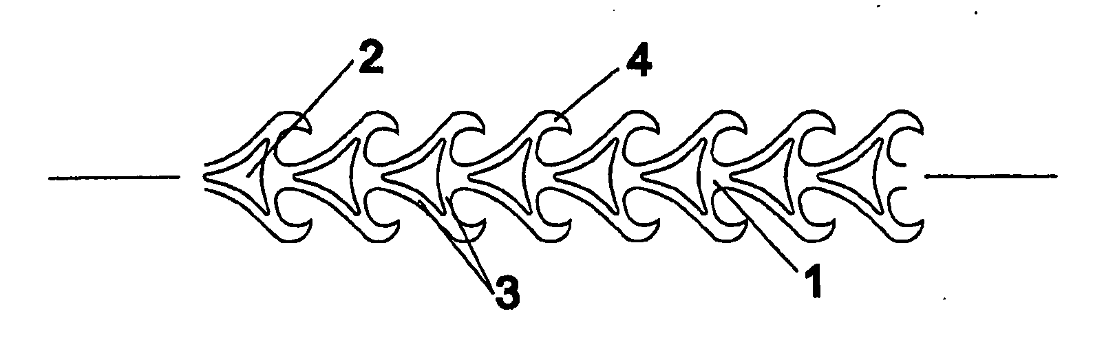
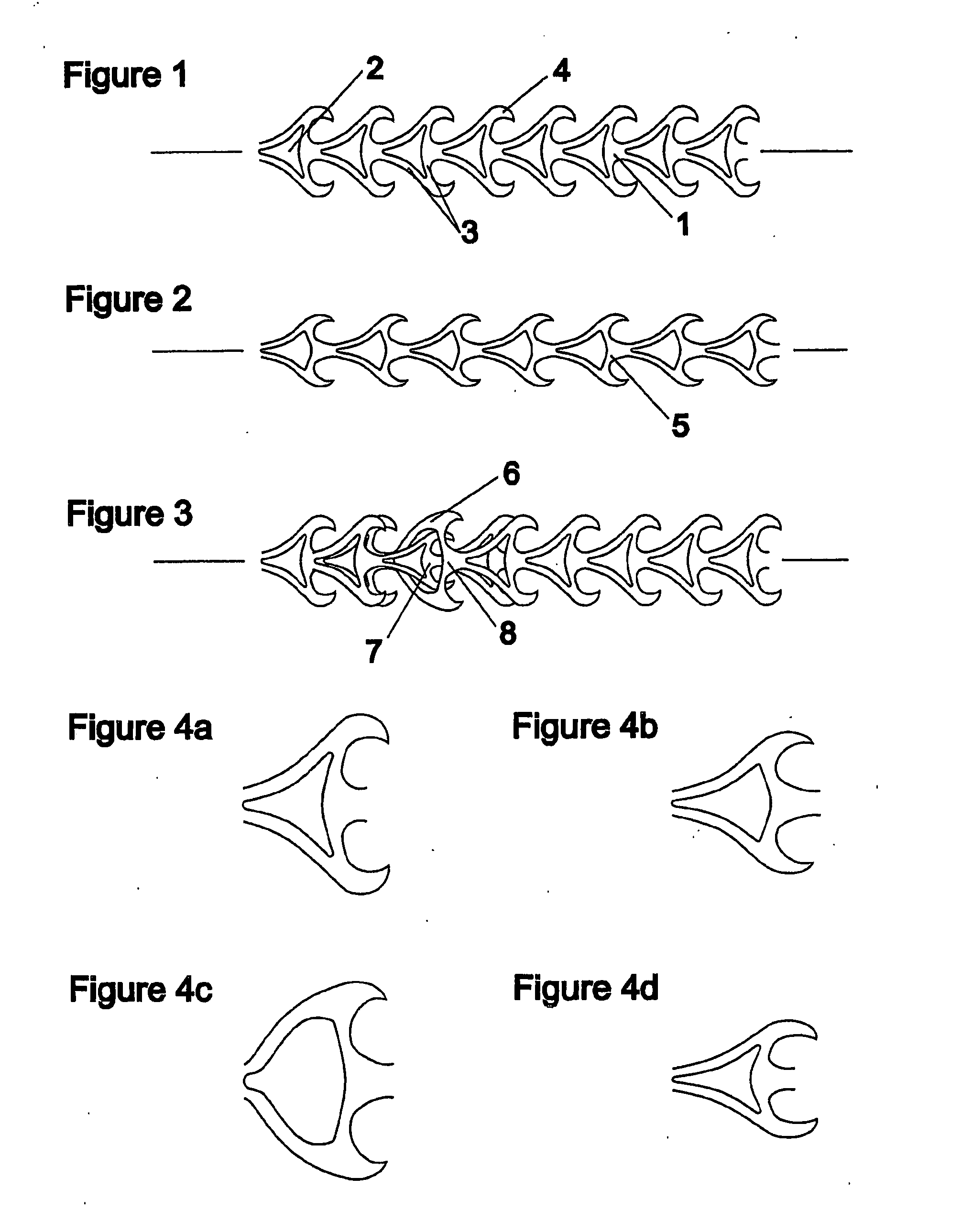
[0053]FIG. 1 portrays a portion of waste-free tie strip in a relaxed state 1 according to existing designs (e.g. prior art U.S. Pat. No. 5,799,376) in which an aperture 2 is bounded by inwardly curved wall portions 3, extending from which are latching members 4.

[0054] When longitudinal tension is applied, the rear wall of each cell bends outwards 5 and the strip generally contracts transversely and extends longitudinally, as shown in FIG. 2.

[0055] The side wall members are also able to bend outwards 6 and this occurs during the insertion of one cell 7 into another 8 (FIG. 3). It is to be noted that in this design the inserted (penetrant) cell 7 generally contracts laterally whereas the penetrated cell 8 generally expands laterally.

[0056] Subsequent to successful penetration of one cell though another, the wall portions return to an inwardly pointing state and the latching members of the inserted cell serve to prevent its withdrawal.

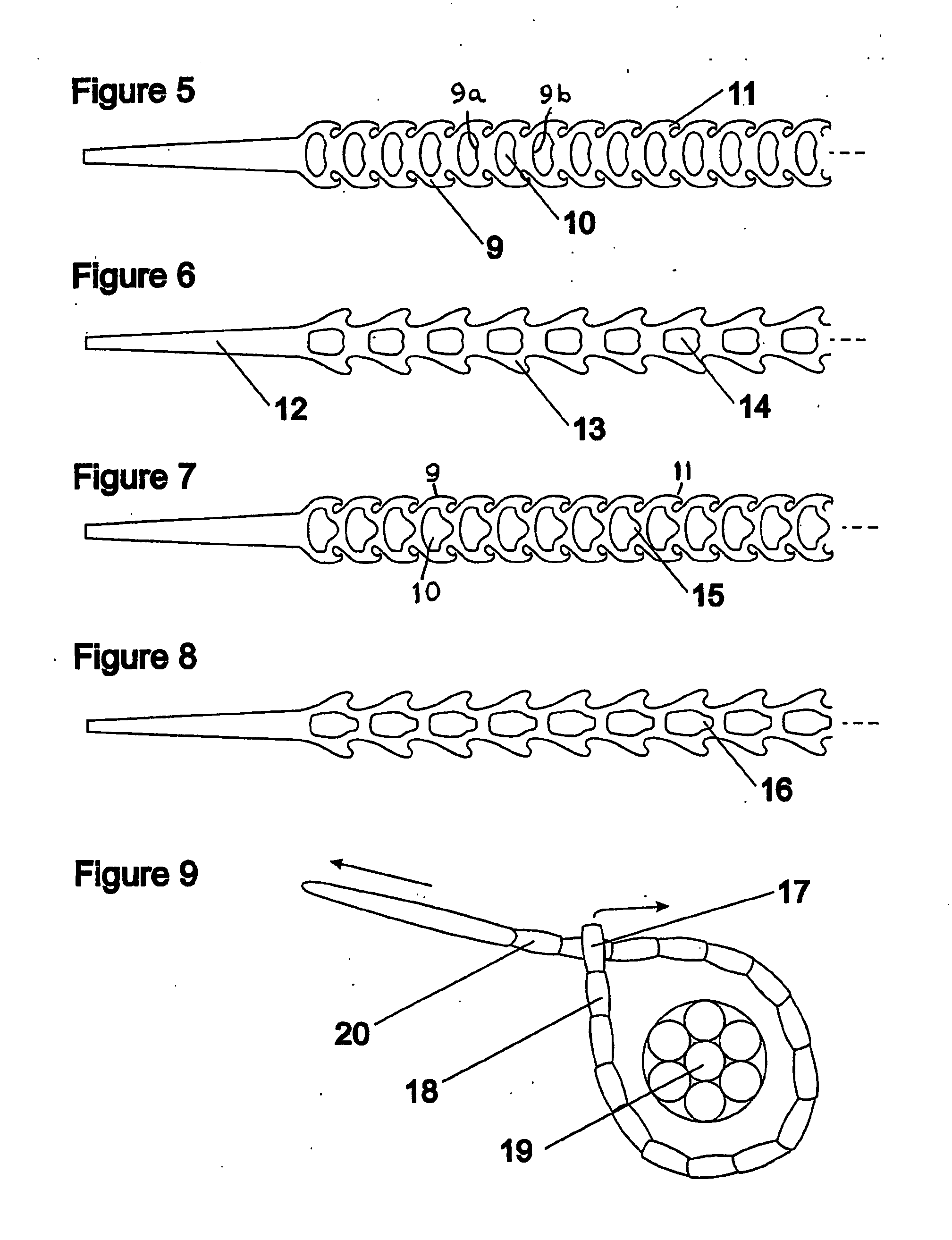
[0057] The full range of two-dimensional cellul...


PUM

PropertyMeasurementUnit
tensile strengthaaaaaaaaaa
tear strengthaaaaaaaaaa
thickaaaaaaaaaa

Abstract

A flexible, integrally formed tie strip for forming a loop when passed through itself comprises a plurality of identical cells formed in a strip, the cells forming generally loop-shaped enclosed apertures (10) bounded by wall portions of the cells, each aperture allowing the passage of further cells through it. The cells are further provided with one or more latching members (11) allowing passage of one cell through another in one direction but preventing passage of the cell in the reverse direction. The walls (9) bounding the apertures can be folded to a saddle shape about radial and longitudinal axes, so as to increase the width of the aperture without stretching the material of the walls, thereby facilitating the passage of a penetrating cell through the aperture of another cell. Moreover the penetrating cell is designed to fold so as to pass through still more easily. This three-dimensional deformation is promoted by a notch (15) in the rear of each aperture wall.

Description

FIELD OF THE INVENTION [0001] The present invention relates to tie strips, for example cable ties or horticultural plant ties. BACKGROUND [0002] Cable ties and other forms of tie strip are used to secure items together quickly and easily. Example uses include bundling cables, sealing bags or binding plants to stakes. [0003] One conventional type of tie strip is a long thin plastic device, with an apertured head at one end, extending from which is a slimmer tail portion. On insertion of the tail portion into the aperture of the head portion, the head engages with one of a series of latches spaced along the tail, and thereby prevents its withdrawal. A closed loop is thus formed by the strip which may be pulled tight around target items to fasten them together. [0004] One significant disadvantage of such a tie strip is that the tail portion pulled through the head during fitting is wasted, because it performs no function and cannot be re-used. Only the tail portion forming the closed l...

Claims


Application Information

Patent Timeline
Patent Type & Authority Applications(United States)
IPC IPC(8): B32B3/10B65D63/10F16L3/233
CPCB65D63/1018B65D2563/105F16L3/233Y10T428/24273Y10T428/24314Y10T24/1408Y10T24/1406Y10T428/24298B65D2563/106B65D63/10B65D63/16
Inventor HARSLEY, ANDREW JOHN
Owner HARSLEY ANDREW JOHN
Why Eureka
Try Eureka