
Automated planning and manufacturing systems

a manufacturing system and automatic technology, applied in the field of automatic manufacturing, can solve the problems of increasing the risk of inaccuracy, and achieve the effects of reducing the risk of inaccuracy, and enhancing the quality of the manufacturing program generated

Inactive Publication Date: 2006-06-15
PANKL GEROLD +1
View PDF6 Cites 47 Cited by
  • Summary
  • Abstract
  • Description
  • Claims
  • Application Information

AI Technical Summary

Benefits of technology

[0013] There is a need for advances in information input and information flow management in custom order processing and execution systems. Such advances may help eliminate (or mitigate) the need for re-keying of information, as such re-keying can lead to inefficiencies and an increased risk of inaccuracies. In addition, with the right advances in these features, the transitions among the various stages of the order processing and execution process can be faster. The quality of the manufacturing program generated may also be enhanced.
[0014] Advances in information input and information flow management can also decrease the lead-time needed to design and manufacture a custom product, and improve the quality of the resulting product. Manufacturing costs may also be reduced.
[0015] With the certain advances in information input and information flow management, the customer is presented with added options and flexibility, e.g., in terms of product customizability and delivery times, and the process can be easier to manage for both the customer and the manufacturer.

Problems solved by technology

Such advances may help eliminate (or mitigate) the need for re-keying of information, as such re-keying can lead to inefficiencies and an increased risk of inaccuracies.

Method used


Image

  • Automated planning and manufacturing systems
  • Automated planning and manufacturing systems
  • Automated planning and manufacturing systems

Examples


Embodiment Construction

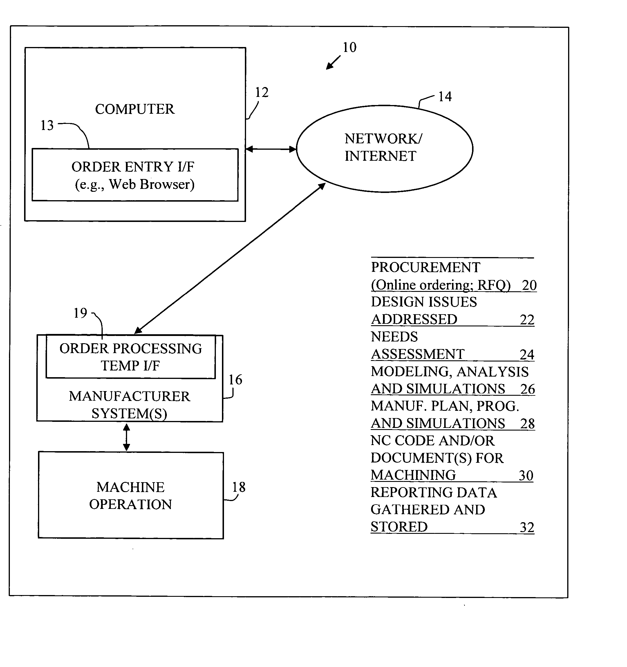
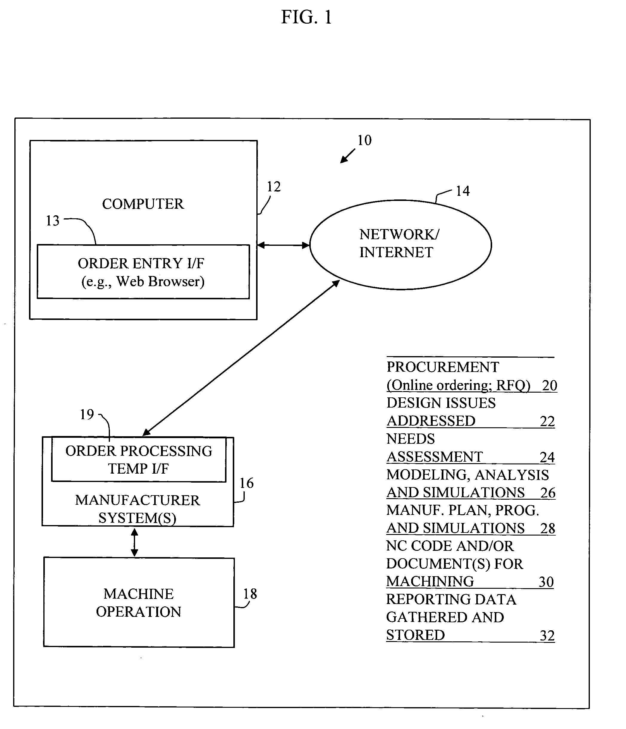
[0039] Referring now to the drawings in greater detail, FIG. 1 is a block diagram of an improved custom order processing and execution system 10. The illustrated system 10 comprises a computer 12 coupled to one or more manufacturer systems 16, via a network 14 (e.g., including the Internet). The computer 12 may be a customer or a manufacturer or manufacturer representative computer.

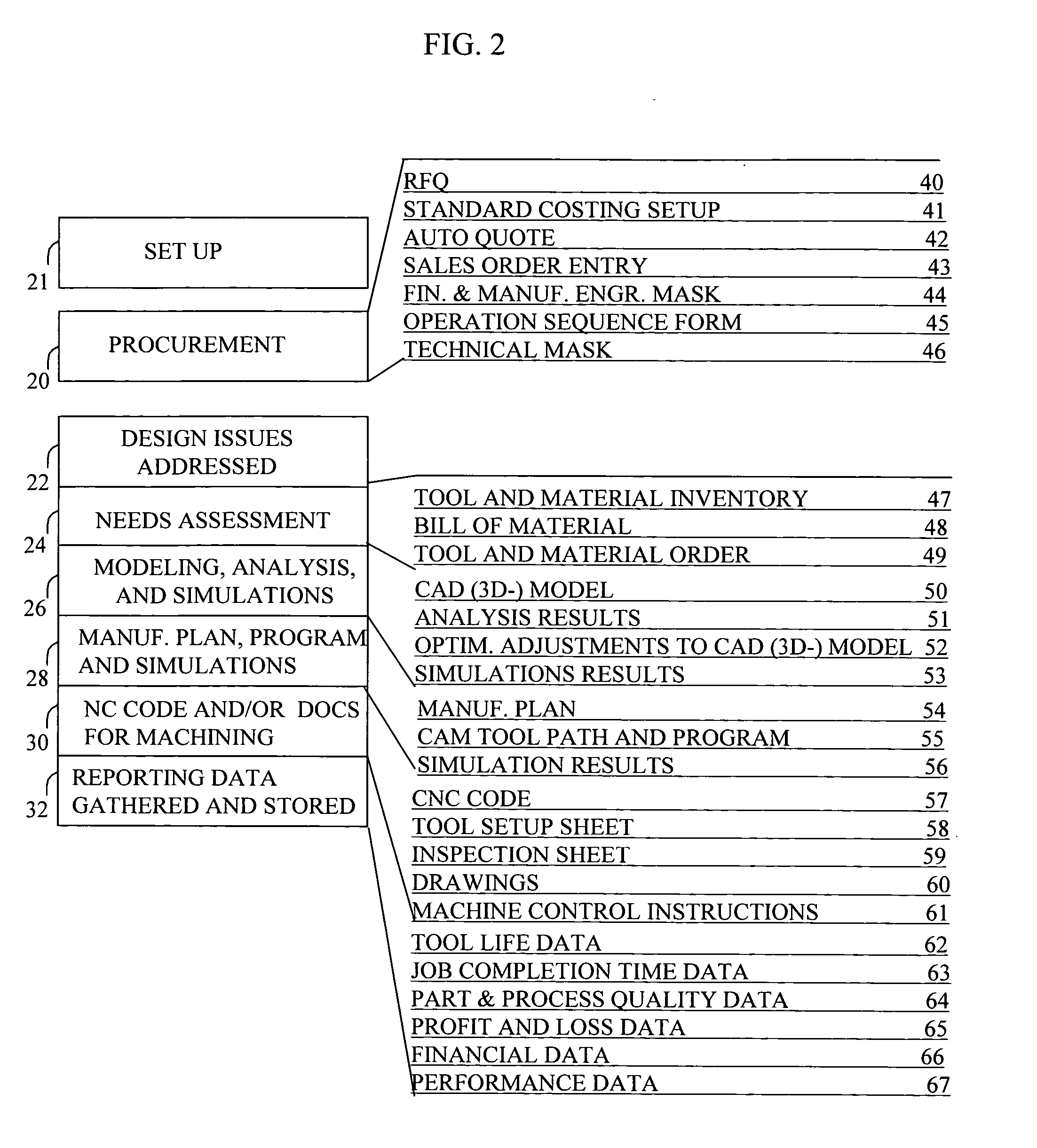
[0040] Manufacturer systems 16 are connected to a machine operation 18. The illustrated custom order processing and execution system 10 may perform or facilitate a number of functions, including those illustrated in FIG. 1 to the right of the diagram. Specifically in a procurement phase 10 of an order-manufacture process, a particular custom part is ordered, and an RFQ (request for quote) is submitted by a customer and responded to. Certain design issues are addressed in phase 22. Such design issues may be addressed by manufacturer systems 16. At a next phase 24, a needs assessment is done, which involve...


PUM


Abstract

A system is provided for part ordering, design, and manufacturing. A manufacturer computer system is provided which comprises a parametric design mechanism to specify geometries of the part with parameters, an intelligent geometry portion, a 3D solid modeling function, and one or more simulation components. The intelligent geometry portion determines machining cycles to manufacture the part. Part-related databases are provided, and order processing components are provided. Such part-related databases and order processing components may form part of one or both of an ERP and PLM computer system. An order processing template is provided to facilitate sales and order processing, tool planning, CA parametric modeling, computer simulation, and the generation of a factory machine program. The order processing template comprises financial and manufacturing engineering planning fields and technical fields. An order template interface, or a set of order template interfaces, is provided. This interface or set of interfaces provides, for a given ordered part, from the order template, CA-specific information to the manufacturer computer system before the manufacturer computer system performs any CAD modeling or CAE calculation of the part. The interface or set of interfaces further provides, for the given ordered part, from the order template, ERP-specific information to the ERP system before the ERP system performs any scheduling of machines and resources, material reservation, or RFQ calculations.

Description

COPYRIGHT NOTICE [0001] This patent document contains information subject to copyright protection. The copyright owner has no objection to the facsimile reproduction by anyone of the patent document or the patent, as it appears in the US Patent and Trademark Office files or records, but otherwise reserves all copyright rights whatsoever. CROSS REFERENCE TO RELATED APPLICATIONS [0002] (Not Applicable) STATEMENT REGARDING FEDERALLY SPONSORED RESEARCH OR DEVELOPMENT [0003] (Not Applicable) BACKGROUND OF THE INVENTION [0004] The present invention relates to certain types of systems for custom manufacturing. [0005] Custom manufacturing involves a customer (e.g., using an online connection via the Internet) electronically communicating his or her preferences for a given product. The customer may even jointly design the end product with the manufacturer. This may be done with the help of a salesperson or distributor representing the customer through the process. [0006] In a custom manufact...

Claims


Application Information

Patent Timeline
IPC IPC(8): G06Q30/00
CPCG06Q30/06G06Q30/0613G06Q30/0635G06Q30/0641
Inventor PANKL, GEROLDNOHTURFFT, NILS A.
Owner PANKL GEROLD
Learn More