Transmitter, signal transfer method, data distribution system and method of same, data receiver, data provider and method of same, and data transferer

Active Publication Date: 2006-06-15
SONY CORP
View PDF5 Cites 0 Cited by
  • Summary
  • Abstract
  • Description
  • Claims
  • Application Information

AI Technical Summary

Benefits of technology

[0011] An object of the present invention is to provide a transmitter and a signal transfer method enabling correct display of an image even if a transmitter for a digital image signal designed for a digital transfer method incorporating encryption technology for copyright protection is connected with a receiver designed for a digital transfer method not incorporating encryption technology for copyright protection.
[0013] Still another object of the present invention is to provide a data receiver used in such a content distribution system, receiving the distributed content data, performing adequate right processing, and outputting the content data in a usable manner.

Problems solved by technology

This is a great advantage for the user, but a problem in terms of protecting the rights of the side providing a movie or other work.
Since the receiver 50 does not have a decryption function however, sometimes the receiver 50 cannot be used for copying content without inviting degradation of the quality of the image etc., for example, it does not have the function of outputting the supplied digital three-primary color image signal or converting the three-primary color image signal to for example an NTSC system video signal for output and therefore cannot display the image of the content even if it is clear that copyright protection is possible.

Method used


Image

  • Transmitter, signal transfer method, data distribution system and method of same, data receiver, data provider and method of same, and data transferer
  • Transmitter, signal transfer method, data distribution system and method of same, data receiver, data provider and method of same, and data transferer
  • Transmitter, signal transfer method, data distribution system and method of same, data receiver, data provider and method of same, and data transferer

Examples


first embodiment

[0049] Below, an explanation will be made of a first embodiment of the present invention by referring to the drawings.

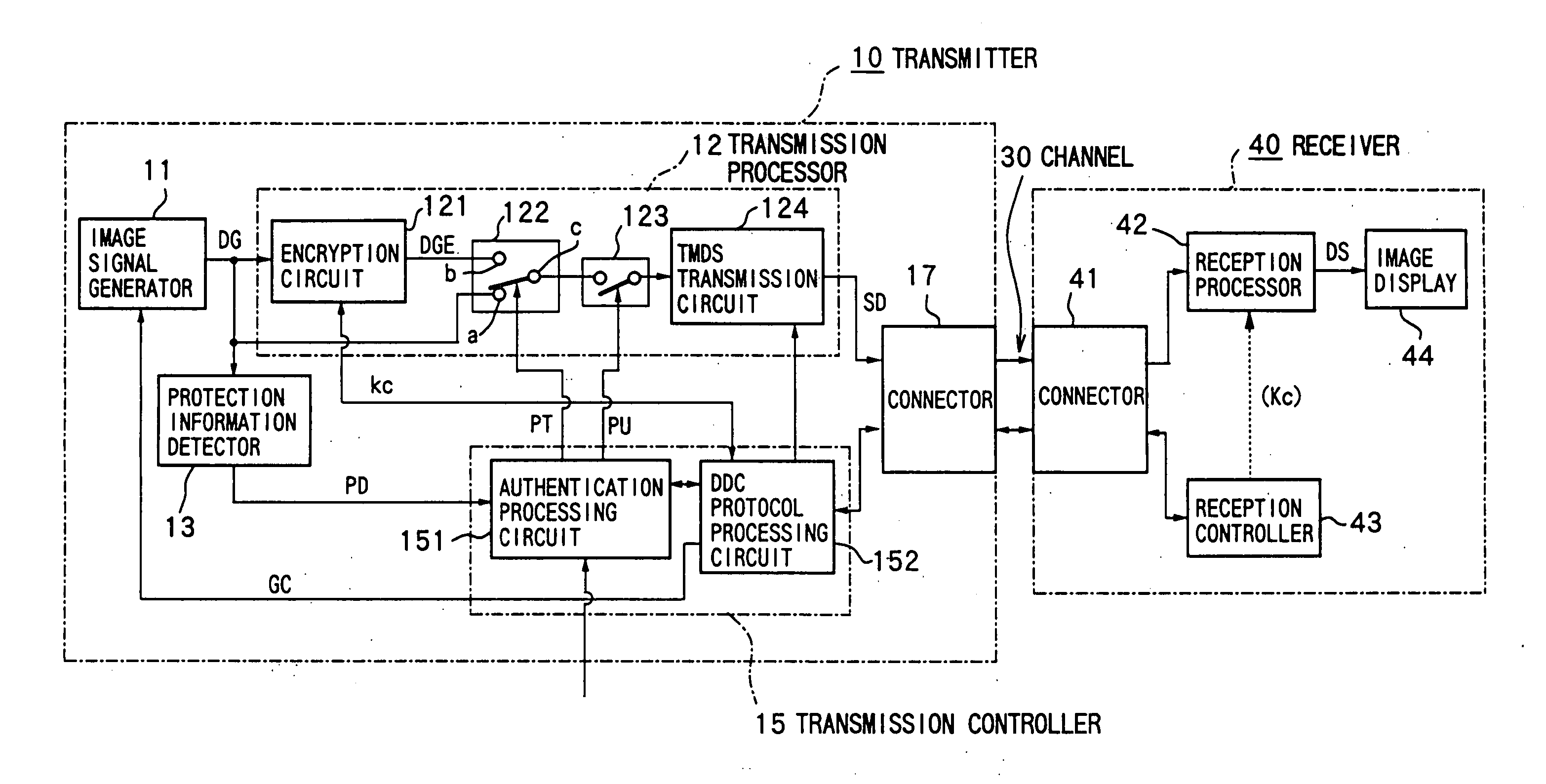
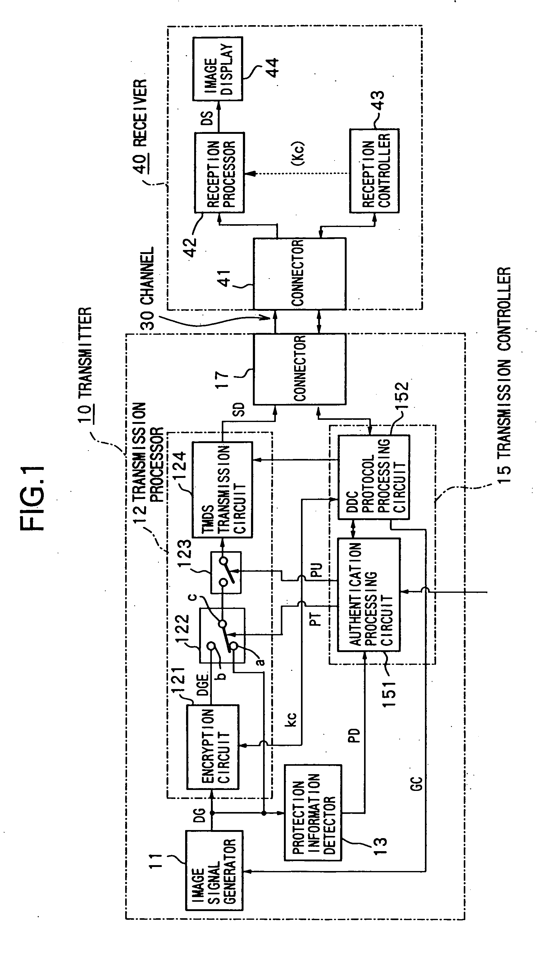
[0050]FIG. 1 is a conceptual view of a signal transfer system for transferring a digital image signal of content. A transmitter (for example a computer system or set top box) 10 for transmitting the image signal and a receiver (display device, television set, etc.) 40 for receiving the image signal and displaying the image are connected via DVI specification channels 30. The DVI specification channels 30 are provided with a TMDS channel for transferring the digital image signal, a bi-directional channel used for DDC (display data channel) specification information transfer relating to plug and play established by the VESA (Video Electronics Standard Association), a power supply line, and a hot plug detection use signal line.

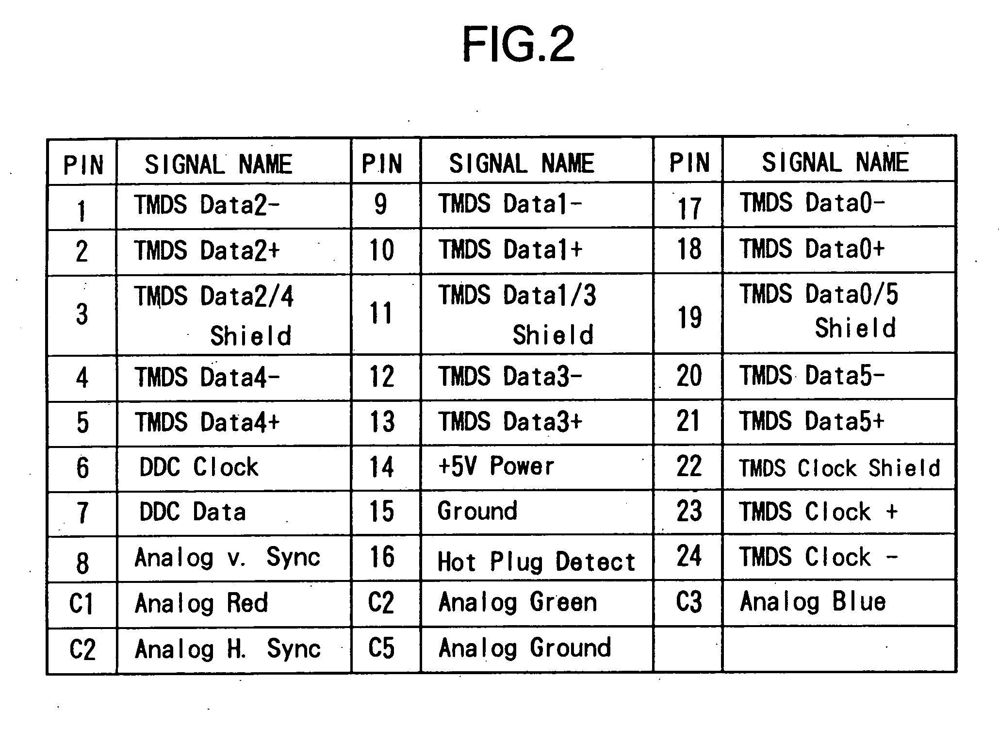
[0051]FIG. 2 is a view of a pin arrangement of a DVI specification connector. Note that the figure shows the case where a channel for transferr...

second embodiment

[0077] Next, the content distribution system and content distribution method enabling a content owner to directly control copying as desired while using a standard apparatus as the processing apparatus after the receiver will be explained as a second embodiment of the present invention by referring to FIG. 13 to FIG. 15.

Overall Configuration

[0078] First, an overall configuration of the content distribution system of the second embodiment will be explained by referring to FIG. 7.

[0079]FIG. 7 is a view of the overall schematic configuration of a content distribution system 1100 of the second embodiment.

[0080] The content distribution system 1100 has a content owner 1200, broadcaster 1300, broadcast network 1400, set top box 1500, display device I / F 1600, and display device 1700.

[0081] First, the configuration of each part will be explained.

[0082] The content owner 1200 is the owner of the content to be distributed, encrypts the content to be distributed by using a desired encryp...

first concrete example

[0100] A first example of concrete application of the content distribution system 1100 will be explained by referring to FIG. 8.

[0101] As the first concrete example, a system wherein the content owner 1200 superimposes the control information for controlling the usage of the content on the content data in the form of an electronic watermark and distributes the same and wherein the usage of the content data received by the user is controlled by this will be illustrated.

[0102]FIG. 8 is a view of the configuration of the content owner 1200 to the set top box 1500 of the first concrete configuration of the content distribution system 1100.

[0103] In the first concrete configuration shown in FIG. 8, the content owner 1200 has an electronic watermark superimposer 1208 which superimposes the copy control information for controlling the usage of the content which becomes valid in the set top box 1500 on the content data in the form of an electronic watermark.

[0104] Further, the content o...


PUM


Abstract

To enable usage of content at a receiver which does not have a copying function even if copyright protection is provided. Model names of receivers not having a function enabling copying of content are held in an authentication processing circuit (151) of a transmitter (10). When a model name obtained from a connected receiver (40) is held, regardless of whether the content is copyright protected, a signal selection circuit (122) selects a terminal a side, a switch (123) is turned on, and an unencrypted signal is transmitted. When a change of the receiver (40) is detected by a hot plug detection function or a plug and play function at a processing circuit (152) during the transfer of a signal of copyright protected content without providing copyright protection, the selection circuit (122) is made to select a terminal b side or the switch (123) is turned off to suspend the transfer of the non-copyright protected signal. The information indicating the receiver is held in a tamper-proof updateable manner.

Description

TECHNICAL FIELD [0001] The present invention relates to a transmitter, signal transfer method, data distribution system and method of same, data receiver, data provider and method of same, and data transferer. More specifically, the present invention relates to a technology for holding in advance information indicating a receiver which does not have the function of being able to copy content using a transferred content signal, and controlling the transfer of a content signal of content or a copyright protected content signal according to whether or not information indicating a connected receiver is included in the held information at the time of transfer of the content. BACKGROUND ART [0002] In the past, a computer system etc. has converted a digital image signal to an analog image signal and supplied the same to a display device by analog transmission. However, along with the spread of display devices for driving displays by using a digital signal, for example, liquid crystal displ...

Claims


Application Information

Patent Timeline
IPC IPC(8): H04L9/00H04N5/00H04N7/16
CPCH04N7/162H04N21/4122H04N21/4367H04N21/44231H04N21/8355H04N21/8358H04N21/4627
Inventor KORI, TERUHIKOFUJII, ASAKO
Owner SONY CORP
Why Eureka
Try Eureka