Startup control method of brushless DC motor

Inactive Publication Date: 2006-06-22
SAMSUNG ELECTRONICS CO LTD
View PDF15 Cites 44 Cited by
  • Summary
  • Abstract
  • Description
  • Claims
  • Application Information

AI Technical Summary

Benefits of technology

[0017] Accordingly, it is an aspect of the present invention to provide a startup control method of a brushless DC (BLDC) motor which is capable of restricting a transient current generated at a startup stage, such that vibration of the BLDC motor that is generated at the startup stage of the BLDC motor, can be reduced.
[0018] It is

Problems solved by technology

Although the device employs a position sensor, such as a Hall sensor, a Resolver sensor, and an encoder, the position sensor causes problems such as an increase of manufacturing cost of the BLDC motor, complication of driving circuits, etc.
However, the conventional senseless operation control method of the BLDC motor requires position information of the rotor to drive the BLDC motor.
Furthermore, the excessive torque pulsation may cause failure of conversion of the senseless operation mode.
However, the conventional method has disadvantages in that, since the BLDC motor must be synchronously accelerated until the ZCP of the back-emf can be detected, it has a high possibility that a transient current can

Method used


Image

  • Startup control method of brushless DC motor
  • Startup control method of brushless DC motor
  • Startup control method of brushless DC motor

Examples


Example

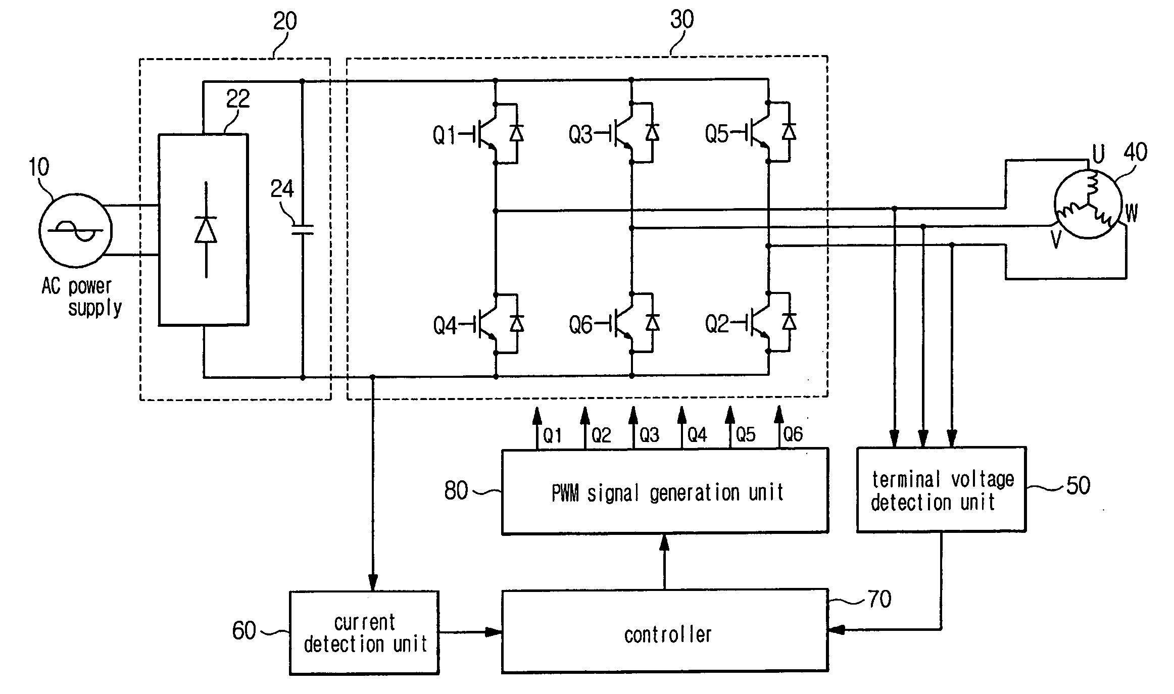
[0046]FIG. 3 is a schematic block diagram illustrating a senseless driving device of a BLDC motor according to a first embodiment of the present invention.

[0047] As shown in FIG. 3, the senseless driving device includes a rectifying unit 20, an inverter 30, a lead voltage detection unit 50, a current detection unit 60, a controlling unit 70 and a PWM signal generation unit 80.

[0048] The rectifying unit 20 rectifies and smoothes AC power 10 to supply DC power to the inverter 30. The smooth rectifying unit 20 includes a rectifier 22 and a smoothing capacitor 24.

[0049] The inverter 30 converts the DC power from the rectifying unit 20 into AC power having three-phases, U, V and W with a variable frequency, in which the AC power is shaped as a pulse, and then supplies the three-phase power to the BLDC motor 40. The inverter 30 is a kind of switching circuit, including six switching elements Q1 to Q6 and diodes.

[0050] The lead voltage detection unit 50 detects a lead voltage of each o...


PUM


Abstract

A startup control method of a BLDC motor is disclosed. The method can control the BLDC motor to prevent the generation of a transient current such that the vibration of the BLDC motor can be reduced at the startup stage and perform a stable conversion into a senseless operation mode such that the startup failure rate of the BLDC motor can be reduced. The startup control method includes commutating a current applied to stator windings according to a rotor position. The method of operating the BLDC motor includes a rotor position that is forcibly aligned and so that phase commutation is performed, a back-electromotive force (back- emf) is detected from a lead voltage of a phase of a voltage which is not applied thereto after performing phase commutation and a determination is performed as to whether the detected back-emf is in a rising interval. The lead voltage of the phase of the voltage which is not applied thereto is integrated, such that if the back-emf is in a rising interval and if an instance that the integration result is greater than a predetermined value a phase commutation time point is setand conversion into a senseless operation mode is performed if the back-emf detected from the lead voltage is in a stable interval, based on a frequency of the voltage applied to the stator winding.

Description

CROSS-REFERENCE TO RELATED APPLICATIONS [0001] This application claims the benefit of Korean Patent Application No. 2004-108214, filed on Dec. 17, 2004 in the Korean Intellectual Property Office, the disclosure of which is incorporated herein by reference. BACKGROUND OF THE INVENTION [0002] 1. Field of the Invention [0003] The present invention relates to a senseless startup control technique of a brushless direct current motor (hereinafter referred to as BLDC motor), and, more particularly, to a method that is capable of controlling a BLDC motor to prevent the generation of transient current in its startup stage. [0004] 2. Description of the Related Art [0005] Generally, a BLDC motor includes a stator as an armature inducing electromotive force (emf) by a current-carrying coil thereof, and a rotor as a permanent magnet having N—S poles, in which the rotor is rotated with respect to the stator. It is necessary to form continuous rotating magnetic field of the BLDC motor such that th...

Claims


Application Information

Patent Timeline
IPC IPC(8): H02P7/06
CPCH02P6/182H02P6/20H02P1/18
Inventor LEE, KWANG WOONKIM, DAE KYONGLEE, SANG TAEKCHOI, HYEN YOUNG
Owner SAMSUNG ELECTRONICS CO LTD
Why Eureka
Try Eureka