Unlock instant, AI-driven research and patent intelligence for your innovation.

Screen, a fresnel lens sheet used for the screen, and an image display apparatus using the screen

a technology applied in the field of screen and lens, can solve the problems of affecting the image quality of the image, so as to reduce the brightness of the change, and reduce the degradation of image quality.

Active Publication Date: 2006-06-22
MAXELL HLDG LTD
View PDF8 Cites 2 Cited by
  • Summary
  • Abstract
  • Description
  • Claims
  • Application Information

AI Technical Summary

Benefits of technology

The invention aims to provide a technology for a thinning image display apparatus that reduces reflection loss and enhances light efficiency to brighten the picture. It proposes a construction with a total reflection prism and a first refractive prism on the light incident surface and a second refractive prism on the picture seen side. The total reflection prism reflects light incident at a predetermined angle or more to have the same outgoing direction as the first refractive prism. The first refractive prism is positioned in a region on the side of the Fresnel lens sheet towards the picture source, and a second total reflection prism portion is formed to reflect light in a second direction perpendicular to the lens sheet. The invention also addresses the issue of discontinuity of light and provides a solution to enhance image quality.

Problems solved by technology

When a image display apparatus is further thinned, the loss is sharply increased to cause a problem that left and right upper ends of a screen become dark.
Since the construction described in WO / 02 / 27399is one, in which refractive prisms are provided on a light incident surface of a Fresnel lens sheet, however, a decrease in efficiency is caused and an intermediate region image (a doughnut-shaped region on a screen), which is especially important as an image, become dark in some cases.
When discontinuity of light is generated, discontinuous portions are produced on a picture as viewed from the front, which makes a factor for degradation in image quality.

Method used


Image

  • Screen, a fresnel lens sheet used for the screen, and an image display apparatus using the screen
  • Screen, a fresnel lens sheet used for the screen, and an image display apparatus using the screen
  • Screen, a fresnel lens sheet used for the screen, and an image display apparatus using the screen

Examples


Embodiment Construction

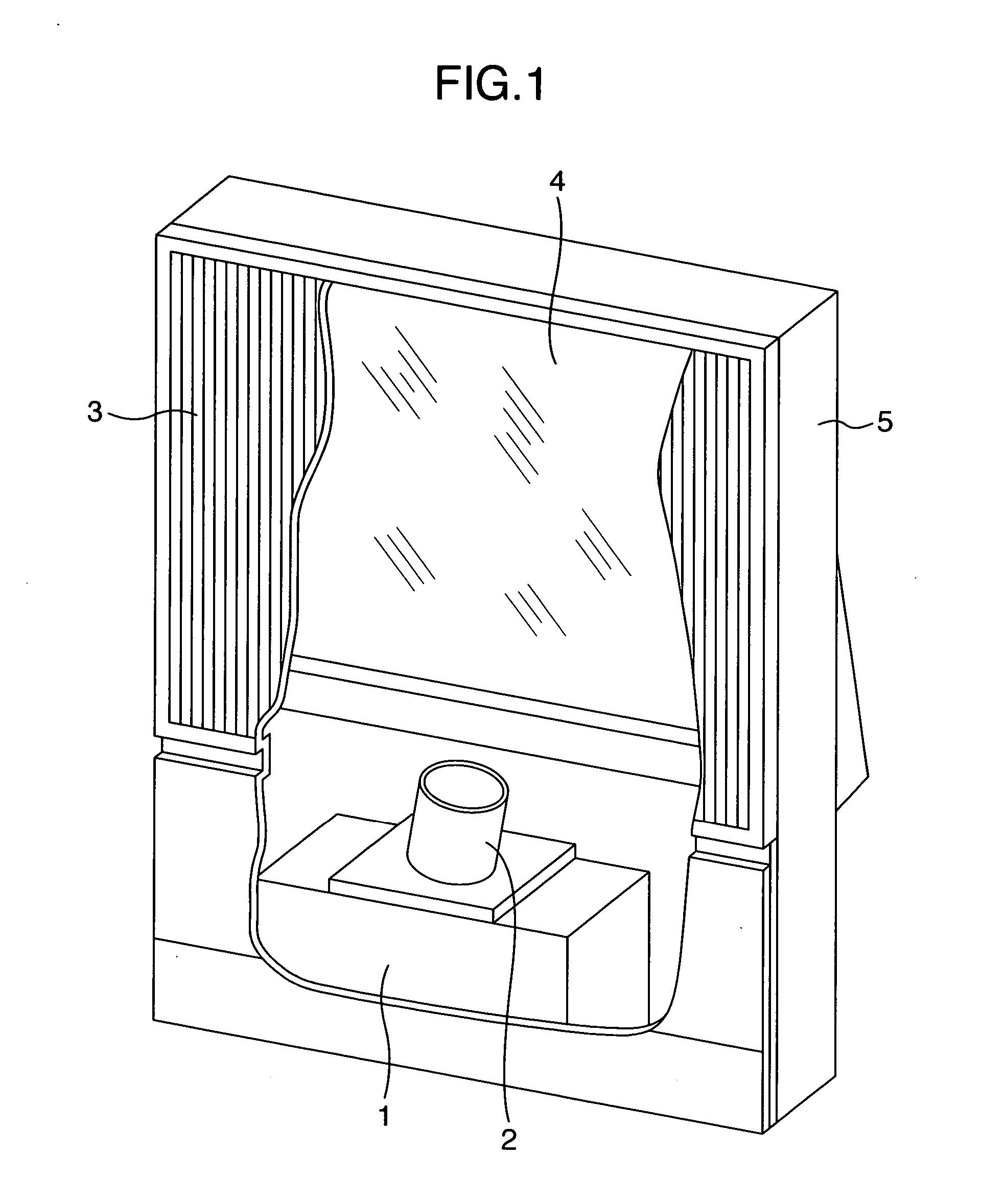
[0037] Embodiments of the invention will be described hereinafter with reference to the drawings. FIG. 1 is a partially sectioned perspective view of a image display apparatus according to the invention. A picture source 1 is structured by a projection type Braun tube, a reflection or transmissive liquid crystal panel, a picture modulation element such as a display element provided with a plurality of fine mirrors, and the like, and displays a small-sized picture. A projection lens 2 projects the picture on a transmissive screen 3. Since generally a distance of projection is long, a reflection mirror 4 is provided midway an optical path so as to reduce a depth of the image display apparatus. These elements are accommodated within a housing 5 and fixed in predetermined positions.

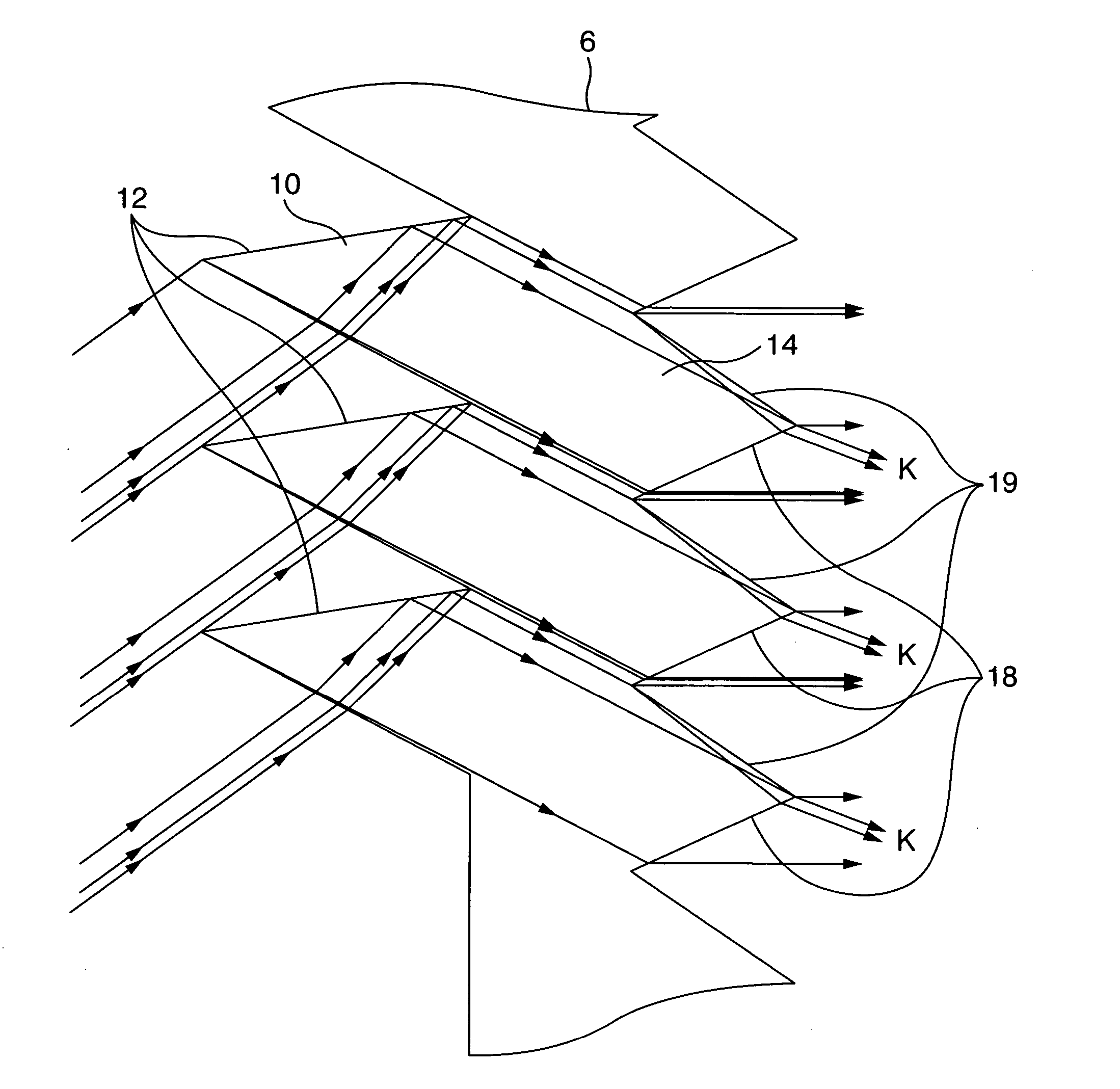
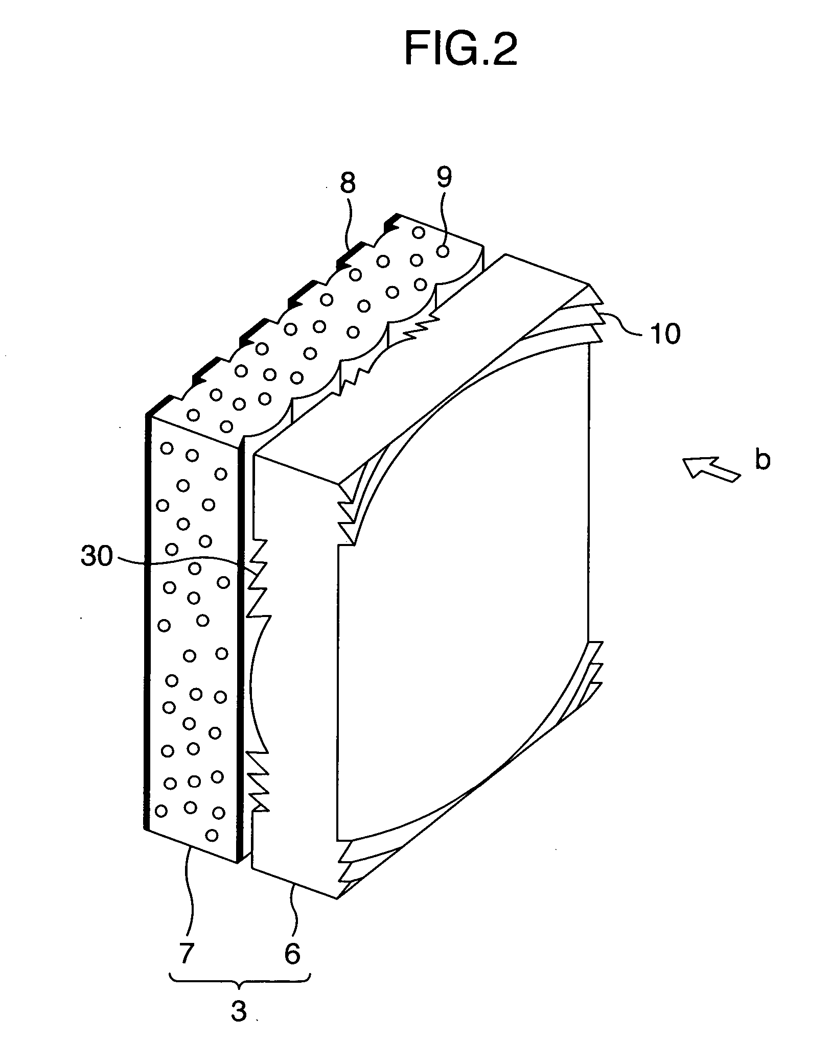
[0038]FIG. 2 is a schematic view showing construction of the transmissive screen 3 according to an embodiment of the invention. An enlarged projection image light (not shown) projected in a direction indicat...


PUM


Abstract

The present invention provides a technology suitable for shortening a depth of a image display apparatus while obtaining a picture of high quality. According to the invention, a total reflection prism portion is provided on a side of a Fresnel lens sheet toward a picture source. The total reflection prism portion reflects an incident light to a direction toward an optic axial center of the Fresnel lens sheet to have the same outgoing. On the other hand, a first refractive prism portion, by which light of a predetermined incident angle or less is refracted to outgo to a direction along an optical axis of the Fresnel lens sheet, and a second refractive prism portion, by which light reflected to the direction toward the optic axial center of the Fresnel lens sheet is changed to the direction along the optical axis.

Description

INCORPORATION BY REFERENCE [0001] The present application claims priority from Japanese application JP 2004-365259 filed on Dec. 17, 2004, the content of which is hereby incorporated by reference into this application. BACKGROUND OF THE INVENTION [0002] (1) Field of the Invention [0003] The present invention relates to an image display apparatus that enlarges and projects an image of a picture source to display the same on a transmissive screen, a screen and a Fresnel lens sheet both used in the image display apparatus. [0004] (2) Description of the Related Art [0005] A projection type image display apparatus (hereinafter, in some cases, referred to as “set”) uses a projection lens, etc. to enlarge a picture displayed on a projection type Braun tube, a liquid crystal display apparatus, etc. as a small-sized picture source to project the same on a transmissive screen, thereby forming a picture on the transmissive screen. [0006] Thinning (reduction of the set in depth dimension) is de...

Claims


Application Information

Patent Timeline
Patent Type & Authority Applications(United States)
IPC IPC(8): G03B21/60G03B21/56G02B5/02G02B5/04G03B21/62
CPCG03B21/10G03B21/625
Inventor YOSHIKAWA, HIROKIOHISHI, TETSUIMAFUKU, DAISUKEHIRATA, KOJI
Owner MAXELL HLDG LTD