Catadioptric projection objective

a catadioptric and objective technology, applied in the field of catadioptric projection objectives, can solve the problems of difficult to provide purely refractive systems with adequate correction of chromatic aberrations, require a great deal of lens material, and only a very limited degree of quality, so as to achieve good correction state, reduce production costs, and save material

Inactive Publication Date: 2006-06-22
CARL ZEISS SMT GMBH
View PDF9 Cites 36 Cited by
  • Summary
  • Abstract
  • Description
  • Claims
  • Application Information

AI Technical Summary

Benefits of technology

[0012] It is one object of the invention to provide a catadioptric projection objective which has a very good correction state and can be produced in a way which saves material. It is

Problems solved by technology

The Abbé constants of these materials are relatively close together, and so it is difficult to provide purely refractive systems with adequate correction of chromatic aberrations.
Such systems also require a great deal of lens material which is available in suitable quality only to a very limited e

Method used


Image

  • Catadioptric projection objective
  • Catadioptric projection objective
  • Catadioptric projection objective

Examples


first embodiment

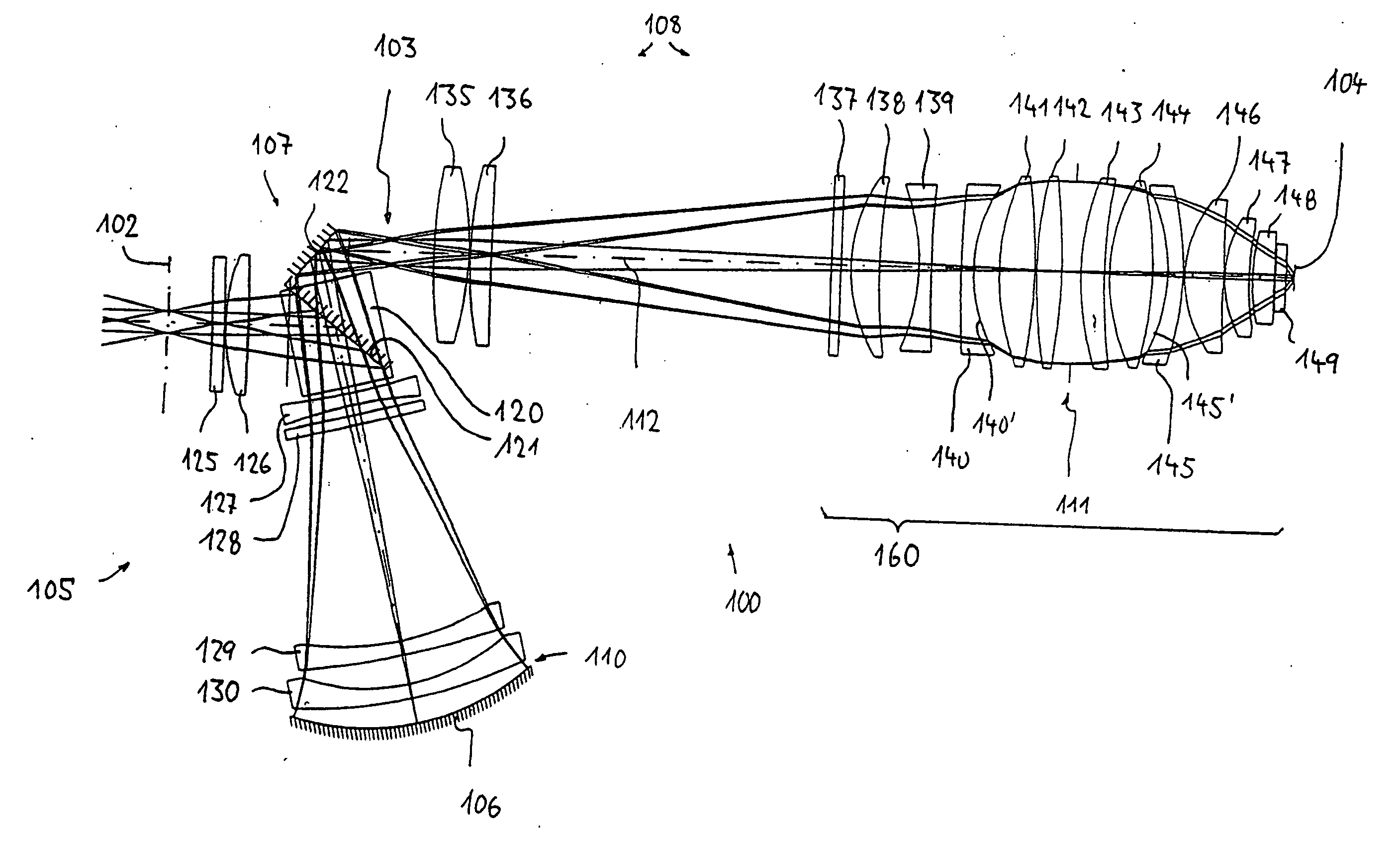
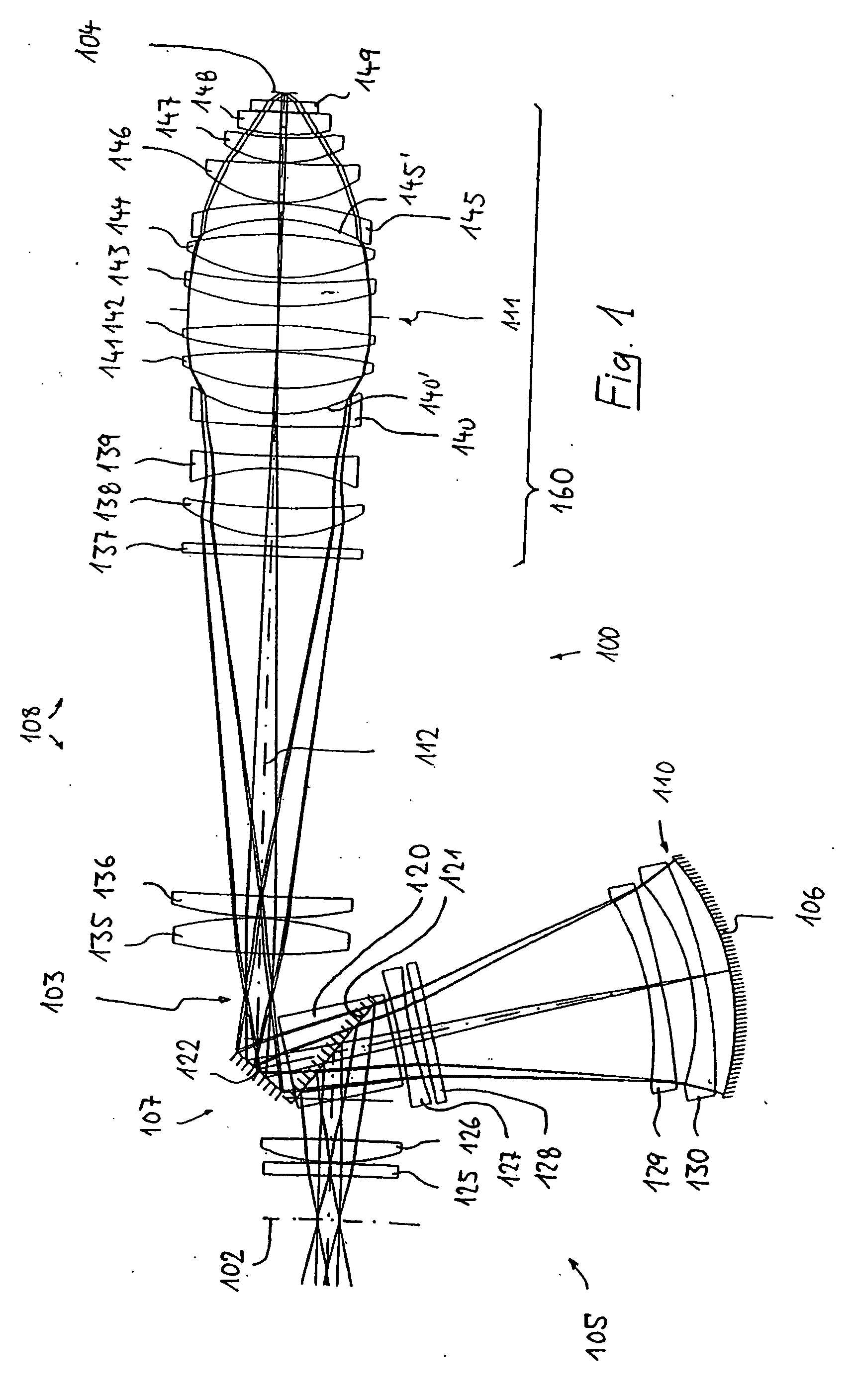
[0049] an inventive catadioptric projection objective 100 with physical beam splitting is shown in FIG. 1. The said objective serves to image a pattern arranged in its object plane 102 into its image plane 104 in a de-magnifying fashion in a scale of 4:1 by producing a real intermediate image 103, and has between the object plane and image plane a catadioptric first objective part 105, with a concave mirror 106, and a beam deflecting device 107 as well as a purely refractive second objective part 108. Since a real intermediate image 103 is produced, two real pupil surfaces 110, 111 are present, the pupil surface 111 closest to the image field being positioned in the region of greatest beam diameter of the refractive part. The site of the pupil surface 111 closest to the image (diaphragm site) is free of lenses, and so a system diaphragm 115 for variably limiting the cross section of the beam passing through the objective can conveniently be provided in this region in order to adjust...

second embodiment

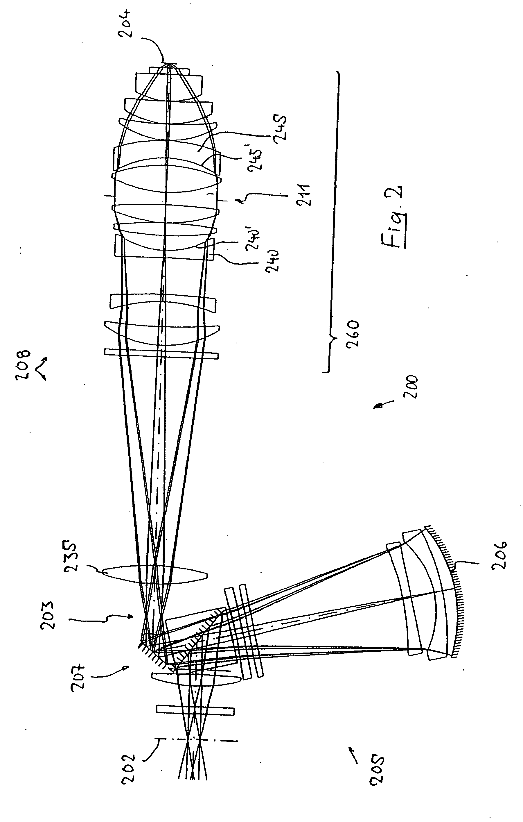
[0065] a catadioptric projection objective 200 with a physical beam splitter is shown in FIG. 2, its specification being given in Tables 4 and 5. The numbering of the optical elements or subassemblies corresponds essentially to the numbering of the embodiment in accordance with FIG. 1 increased by 100. A similar statement holds for FIGS. 3 and 4 with increases by 200 and 300, respectively.

[0066] As in the case of the embodiment in accordance with FIG. 1, a concave lens 240 designed as a negative meniscus lens and having a concave surface 240′ directed towards the pupil surface 211 is arranged in the divergent beam path upstream of the pupil surface 211 near the image. A further concave lens (negative meniscus lens 245 with an entrance surface 245′ concave towards the pupil surface 211) curved relative to the beam path is arranged in the convergent beam path between the pupil surface 211 and image plane 204. The large sines, occurring at the surfaces 240′245′, of the angles of incide...

embodiment 400

[0071] The embodiment 400 in accordance with FIG. 4 differs in essence from objective 300 in terms of the folding geometry. Here, the light coming from the object plane 402 firstly strikes the concave mirror 400, by which it is reflected, in the direction of the deflecting mirror 409 required for functioning. After the folding there and the passage through the positive lens 435, a second folding, which permits parallel positioning of the object plane 402 and image plane 404, takes place at the plane mirror 410. Reference is made to the description relating to FIG. 3, and to the corresponding tables, for the other characteristics.

[0072] The embodiments illustrated by way of example have further advantageous special features, of which a few are mentioned below. In the systems with a physical beam splitter (FIGS. 1 and 2), the intermediate image is not situated on or in the vicinity of an optical surface but at a large spacing downstream of a folding mirror or upstream of the entrance ...


PUM


Abstract

A catadioptric projection objective for imaging a pattern arranged in the object plane (102) of the projection objective into the image plane (104) of the projection objective has a catadioptric first objective part (105) having at least one concave mirror (106), and a dioptric second objective part (108) in which there is situated a pupil surface (111) near the image. At least one concave lens (140, 145) with a concave surface (140′, 145′) directed towards the pupil surface (111) is arranged in a near zone (160) of the pupil surface. There are no lenses with a strongly curved concave surface directed towards the image plane between the pupil surface and the image plane. Such projection objectives can be produced in a way which saves material in conjunction with good optical correction, and are relatively insensitive to production-induced deviations from the ideal design.

Description

[0001] This application is a Continuation of International Patent Application PCT / EP2004 / 003708 filed on Apr. 7, 2004 and claiming priority from German Patent Application DE 103 16 428.6 filed on Apr. 8, 2003. Priority is claimed from German Patent Application DE 103 16 428.6 filed on Apr. 8, 2003. The disclosure of these applications is incorporated herein entirely by reference.BACKGROUND OF THE INVENTION [0002] 1. Field of the Invention [0003] The invention relates to a catadioptric projection objective for imaging a pattern arranged in an object surface of the projection objective into an image surface of the projection objective. [0004] 2. Description of the Related Art [0005] Such projection objectives are used in projection exposure machines for fabricating semiconductor components and other finely structured devices, in particular in wafer scanners and wafer steppers. They serve for projecting patterns of photomasks or lined plates, generally referred to below as masks or ret...

Claims


Application Information

Patent Timeline
IPC IPC(8): G02B17/00G02B17/08G03F7/20
CPCG02B17/08G02B17/0892G03F7/70225G03F7/70275
Inventor EPPLE, ALEXANDERDODOC, AURELIAN
Owner CARL ZEISS SMT GMBH
Why Eureka
Try Eureka