Refractive projection objective for immersion lithography

a technology of refractive projection and objective, which is applied in the direction of photomechanical equipment, instruments, printers, etc., can solve the problems of difficult attempts to achieve yet higher apertures, difficult fabrication of projection objectives, and inconvenient operation of optical systems, etc., to achieve good correction state and compact overall size

Inactive Publication Date: 2007-03-06
CARL ZEISS SMT GMBH
View PDF11 Cites 68 Cited by
  • Summary
  • Abstract
  • Description
  • Claims
  • Application Information

AI Technical Summary

Benefits of technology

[0015]One of the objects of the invention is to provide a refractive projection objective that is suitable for immersion lithography. It is another object to provide a refractive projection objective that has a compact overall size. It is another object to provide a refractive projection objective that can be produced with acceptable use of materials. It is another object to provide a refractive projection objective that has a good correction state for chromatic aberrations, in particular for lateral chromatic aberrations.

Problems solved by technology

The optical system may not be suitable for use in the series production of semiconductors or the like.
Attempts to achieve yet higher apertures are rendered difficult because the maximum lens diameters increase dramatically as apertures become larger, and this complicates the fabrication of the projection objectives, making it more expensive.
In addition, the chromatic aberrations and here, in particular, the lateral chromatic aberrations assume disturbing values.
However, in the wavelength region of the deep ultraviolet (DUV) at operating wavelengths of less than 200 nm only a few transparent optical materials with sufficiently low absorption are available.
However, said fluoride crystal materials are available only to a limited extent, expensive and difficult to work.

Method used


Image

  • Refractive projection objective for immersion lithography
  • Refractive projection objective for immersion lithography
  • Refractive projection objective for immersion lithography

Examples


Embodiment Construction

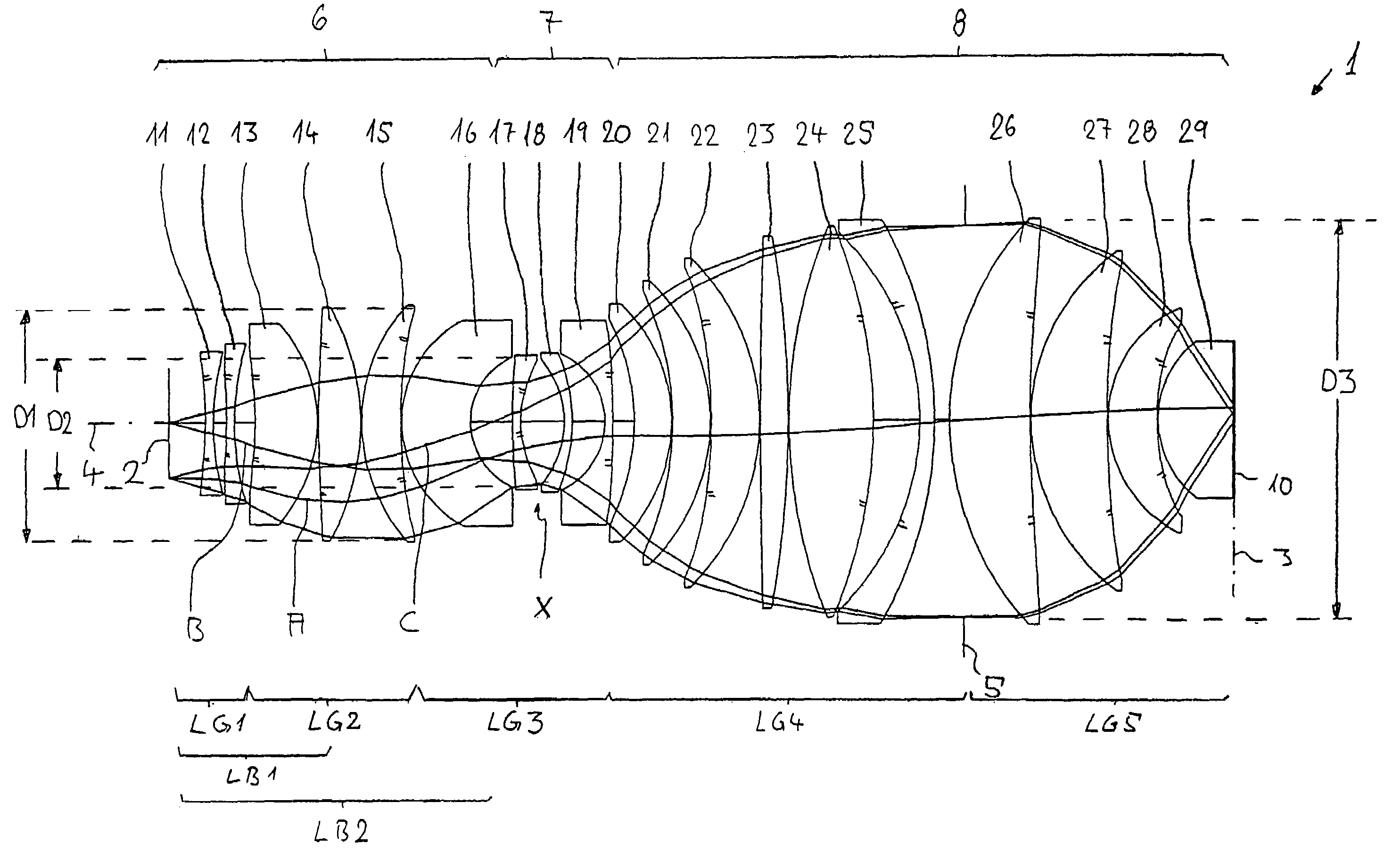
[0057]In the following description of the preferred embodiments, the term “optical axis” denotes a straight line through the centers of curvature of the optical components. Directions and distances are described as on the image side or towards the image, when they are directed in the direction of the image plane or the substrate which is located there and is to be exposed, and as on the object side or towards the object when they are directed towards the object with reference to the optical axis. In the examples, the object is a mask (reticle) with the pattern of an integrated circuit, but another pattern, for example a grating, can also be involved. In the examples, the image is formed on a wafer serving as substrate and coated with a photoresist layer, but other substrates are also possible, for example elements for liquid crystal displays or substrates for optical gratings. The specified focal lengths are focal lengths with reference to air.

[0058]A typical design of an embodiment...


PUM

PropertyMeasurementUnit
operating wavelengthaaaaaaaaaa
wavelengthsaaaaaaaaaa

Abstract

A purely refractive projection objective suitable for immersion microlithography is designed as a single-waist system with five lens groups, in the case of which a first lens group with negative refractive power, a second lens group with positive refractive power, a third lens group with negative refractive power, a fourth lens group with positive refractive power and a fifth lens group with positive refractive power are provided. A constriction site of narrowest constriction of the beam bundle lies in the region of the waist. A waist distance AT exists between the object plane and the constriction site X. The condition AT / L≦0.4 holds for a distance ratio AT / L between the waist distance AT and an object-image distance L of the projection objective. Embodiments of inventive projection objectives reach very high numerical apertures NA>1.1 in conjunction with a large image field and are distinguished by a compact overall size and good correction of the lateral chromatic aberration.

Description

[0001]The present application is a Continuation-in-Part of application Ser. No. 10 / 734,623, filed Dec. 15, 2003 now U.S. Pat. No. 6,995,930; which is a Continuation-in-Part Application of prior application Ser. No. 09 / 751,352, filed Dec. 27, 2000 now U.S. Pat. No. 6,665126, which, in turn, claims the benefit of Provisional Application No. 60 / 173,523, filed Dec. 29, 1999, and of Provisional Application No. 60 / 222,798, filed Aug. 2, 2000; Application No. 10 / 734,623 additionally claims the benefit of Provisional Application No. 60 / 511,673, filed Oct. 17, 2003; the present application additionally claims the benefit of U.S. Provisional 60 / 530,623, filed Dec. 19, 2003, U.S. Provisional 60 / 530,978, filed Dec. 22, 2003, U.S. Provisional, 60 / 544,967, filed Feb. 13, 2004, U.S. Provisional 60 / 568,006, filed May 4, 2004, U.S. Provisional 60 / 591,775, filed Jul. 27, 2004, U.S. Provisional 60 / 592,208, filed Jul. 29, 2004, U.S. Provisional 60 / 612,823, filed Sep. 24, 2004, and German Patent Applica...

Claims


Application Information

Patent Timeline
Patent Type & Authority Patents(United States)
IPC IPC(8): G02B9/00G02B9/60G03B27/54G02B13/14G02B13/18G02B17/08G03F7/20
CPCG02B13/143G02B13/18G02B15/177G03F7/70341G02B27/0025G03F7/70241G02B21/33
Inventor ROSTALSKI, HANS-JUERGENDODOC, AURELIANEPPLE, ALEXANDERBEIERL, HELMUT
Owner CARL ZEISS SMT GMBH
Why Eureka
Try Eureka