Fuel cell humidification system

a technology of fuel cell and humidification system, which is applied in the direction of fuel cells, solid electrolyte fuel cells, electrical equipment, etc., can solve the problems of difficult to ensure that the fuel cell stack will operate efficiently under all the possible operating conditions, dry out, and most known humidification techniques are poorly designed to respond, etc., to achieve efficient humidification of both cathodes, improve the effect of efficiency and simple implementation

Inactive Publication Date: 2006-06-22
HYDROGENICS CORP
View PDF6 Cites 22 Cited by
  • Summary
  • Abstract
  • Description
  • Claims
  • Application Information

AI Technical Summary

Benefits of technology

[0015] The present invention advantageously provides a fuel cell humidification system having combined the features derived from various humidification methods to achieve an efficient humidification of both cathode and anode streams, with a relatively simple implementation, which is particularly beneficial to small fuel cells. The present invention further advantageously provides a simple method for controlling humidification of both the anode and cathode of a fuel cell. All these features are particularly desirable for vehicular applications.

Problems solved by technology

Nonetheless, it is possible for the flow of gas across the cathode side to be sufficient to remove this water, resulting in drying out on the cathode side as well.
All of these requirements are exceedingly demanding and make it difficult to ensure that a fuel cell stack will operate efficiently under all the possible ranges of operating conditions.
While the key issues are ensuring that a fuel cell power unit can always supply a high power level and at a high efficiency and simultaneously ensuring that it has a long life, accurately controlling humidity levels within the fuel cell power unit is necessary to meet these requirements.
Most known techniques of humidification are poorly designed to respond to rapidly changing conditions, temperatures and the like.
Many known systems can provide inadequate humidification. levels and may have high thermal inertia and / or large dead volumes, so as to render them incapable of rapid response to changing conditions.
However, this patent still fails to fully utilize the waste humidity from fuel cell exhaust.
The fuel humidity retention subsystem is complicated and needs additional devices, which is not desirable for a compact fuel cell configuration.

Method used


Image

  • Fuel cell humidification system
  • Fuel cell humidification system
  • Fuel cell humidification system

Examples


Embodiment Construction

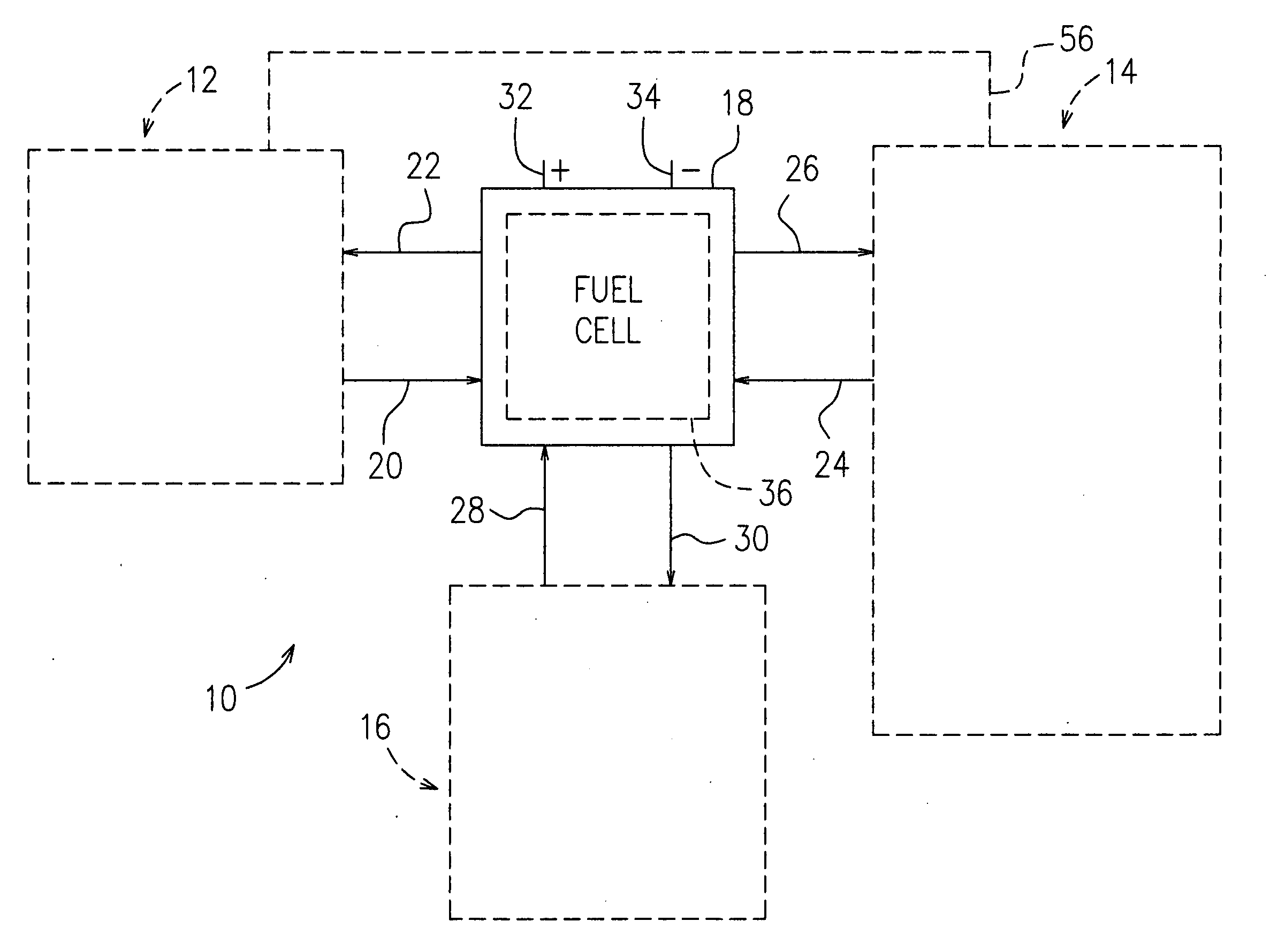
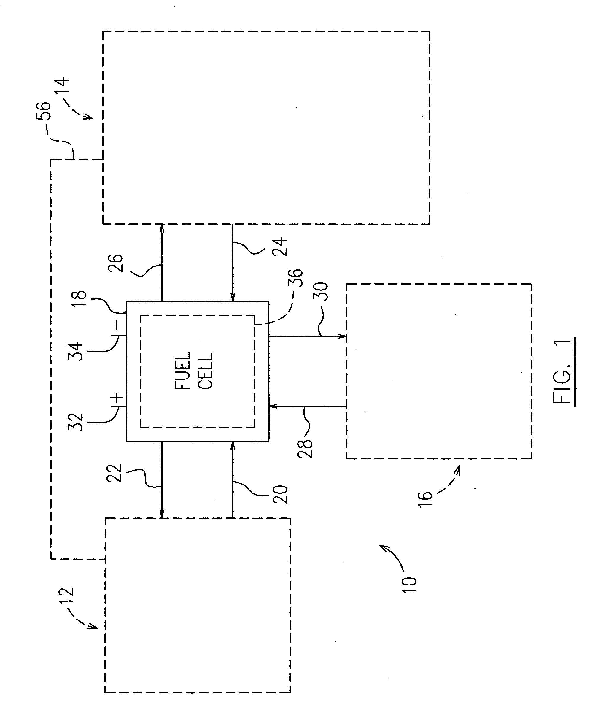
[0023]FIG. 1 illustrates a fuel cell gas management system 10 of the present invention, according to one preferred embodiment. The gas management system 10 generally comprises a cathode humidification system 12, a anode humidity retention system 14 and a cooling water processing system 16, all connected to a fuel cell 18. The fuel cell 18 generally comprises a cathode stream inlet 20, a cathode stream outlet 22, an anode stream inlet 24, an anode stream outlet 26, a cooling water inlet 28 and a cooling water outlet 30. Electricity generated by the fuel cell 18 is conducted to a load (not shown) by conductors 32 and 34. The fuel cell 18 can be used to supply electrical power for a variety of applications. For example, the fuel cell 18 can be used to recharge the batteries of an electric automobile or can be used as a power source for commercial or household electrical services.

[0024] The fuel cell 18 generally operates according to known methods, and may be any one of a number of kn...


PUM

PropertyMeasurementUnit
lengthaaaaaaaaaa
humidityaaaaaaaaaa
pressureaaaaaaaaaa

Abstract

The present invention provides a fuel cell humidification system comprising features of a cathode humidification system, an anode humidity retention system and a countercurrent flow arrangement of the fuel and air streams in the fuel cell, which performs efficiently and is configured particularly for small fuel cells. The present invention further provides a simple method for controlling both cathode and anode humidification using the fuel cell humidification system of the present invention.

Description

FIELD OF THE INVENTION [0001] The present invention relates generally to fuel cells, and more particularly relates to a fuel cell humidification system and a method used with the system for controlling both cathode and anode humidification. BACKGROUND OF THE INVENTION [0002] Fuel cell systems are seen as a promising alternative to traditional power generation technologies due to their low emissions, high efficiency and ease of operation. Fuel cells convert chemical energy into electrical energy. Proton exchange membrane fuel cells comprise an anode, a cathode, and a selective electrolytic membrane disposed between the two electrodes. In a catalyzed reaction, a fuel such as hydrogen, is oxidized at the anode to form cations (protons) and electrons. The ion exchange membrane facilitates the migration of protons from the anode to the cathode. The electrons cannot pass through the membrane and are forced to flow through an external circuit, thus providing an electrical current. At the c...

Claims


Application Information

Patent Timeline
Patent Type & Authority Applications(United States)
IPC IPC(8): H01M8/04
CPCH01M8/04097H01M8/04104H01M8/04141H01M8/04149Y02E60/50
Inventor TOTH, AKOS
Owner HYDROGENICS CORP
Why Eureka
Try Eureka