Wireless communication system using a plurality of antenna elements with adaptive weighting and combining techniques

a technology of antenna elements and wireless communication, applied in the field of wireless communication systems, can solve the problems of multipath interference effects, wlan performance can be greatly degraded, wlans often fall short of the expected operating range, etc., and achieve the effect of reducing interference arrival, increasing operating range, and simplifying interfa

Inactive Publication Date: 2006-06-22
RENDA TRUST
View PDF17 Cites 101 Cited by
  • Summary
  • Abstract
  • Description
  • Claims
  • Application Information

AI Technical Summary

Benefits of technology

[0026] In an embodiment of the present invention, the antenna weight is implemented using a modulator. The modulator uses two baseband control signals to create phase shift and amplitude scaling in the signal. In contrast, conventional approaches use a phase shifter and variable gain amplifier. An advantage of the present invention is that the baseband control signals can be directly obtained from processing without the needs for converting the two signals into phase shift and amplitude scaling.
[0027] In the present invention, the antenna weights and combining are performed at the RF frequency, RF combining, instead of at the baseband. Accordingly, in an embodiment of the present invention, a beam former is located between the antenna and the receiver / transmitter interface. RF combining simplifies the interface between the beam former and the transmitter / receiver. Typically, this interface is the same for most vendors whereas the baseband interface differs from vendors to vendors. Accordingly, the approach of the present invention enables beam former processing to be compatible with most vendors.
[0028] In an embodiment of the present invention, an antenna weight magnitude control loop is used to maintain the magnitude of the antenna weight. Accordingly, the receiver sensitivity can be maintained and the circuit will not saturate.
[0029] The present invention provides substantial increase in operating range in a multipath-rich environment; an adaptive antenna null formation, which suppresses the interference arriving from directions other than the desired signal; a reduced deployment effort; cost effectiveness; power efficiency; process, temperature, component variation insensitivity; compactness; fast convergence; and compatibility with existing WLAN systems by exploiting the spatial and polarization antenna diversity, optimal signal combining, and blind weight adaptation.
[0030] The invention will be more fully described by reference to the following drawings.

Problems solved by technology

It has been found that WLANs often fall short of the expected operating range when actually deployed.
In particular, WLAN performance can be greatly degraded by direct and multipath radio interference.
Similarly, in any indoor wireless system, multipath interference effects occur when the transmitted signal is reflected from objects such as walls, furniture, and other indoor objects.
In exchange for this license-free environment, users implementing the IEEE 802.11 b / g and IEEE 802.11a standards are subject to interference from other users of the bands.
The 2.4 to 2.4835 GHz ISM band is particularly sensitive to interference because it is populated with numerous wireless networking products such as Bluetooth systems, HomeRF systems, IEEE 802.11b WLAN devices, microwave ovens, and cordless phones that can result in significant interference.
This interference is the result of a myriad of incompatible data transmission techniques, uncoordinated usage of spectrum, and over-subscription of the available spectrum.
The operation of FHSS systems at wider bandwidths has the potential to increase interference between DSSS and FHSS products.
The interference level of narrowband FHSS systems on DSSS transmission has already been found to be severe.
The channel re-use factor imposes a severe restriction on implementation of 802.11b / g based systems which requires significantly more effort in the network deployment, and increases the chances of interference and packet collision especially within an environment with a dense user cluster, such as in an office building.
The drawback of the selection diversity approach using a single shared receiver is that fast antenna switching and signal quality comparison is required.
The disadvantage of the open loop implementation is that the errors in antenna weights can accumulate over the signal processing steps.
If there is any error in the derived antenna weights, the system can not detect the error automatically since there is no feedback mechanism.
In addition, the system needs to detect the signal arrival and automatically activate the open loop antenna weight estimation process and update the antenna weight upon completion of the required steps, which increases the complexity of the system.
Another disadvantage of the open loop implementation occurs when the initial set of antenna weights happen to produce a combined signal whose power is significantly lower than those from individual antenna.
The antenna weight thus derived can thus have significant error due to the low signal level of the combined signal.
Signal combining techniques typically achieve better performance than the selection diversity antenna approach at the expense of added implementation complexity.
Signal combining techniques typically achieve better performance than the selection diversity antenna approaches at the expense of added implementation complexity.
The use of CMA algorithm as described above has problems distinguishing the desired signal from the interfering signals.
This technique also has problems distinguishing the desired signal from interfering signals.

Method used


Image

  • Wireless communication system using a plurality of antenna elements with adaptive weighting and combining techniques
  • Wireless communication system using a plurality of antenna elements with adaptive weighting and combining techniques
  • Wireless communication system using a plurality of antenna elements with adaptive weighting and combining techniques

Examples


Embodiment Construction

[0053] Reference will now be made in greater detail to a preferred embodiment of the invention, an example of which is illustrated in the accompanying drawings. Wherever possible, the same reference numerals will be used throughout the drawings and the description to refer to the same or like parts.

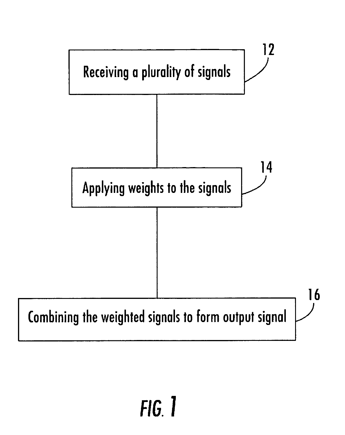
[0054]FIG. 1 is a flow diagram of a method for operating a wireless communication beam forming receiver 10 in accordance with the teachings of the present inventions. In block 12, a plurality of signals are received by the wireless communication receiver. In block 14, weights are applied to the plurality of signals. In block 16, the weighted signals are combined to form an output signal. The weights used in the weighting step are adjusted to increase power in output signal of in-band components and decrease power in the signal out-of-band components.

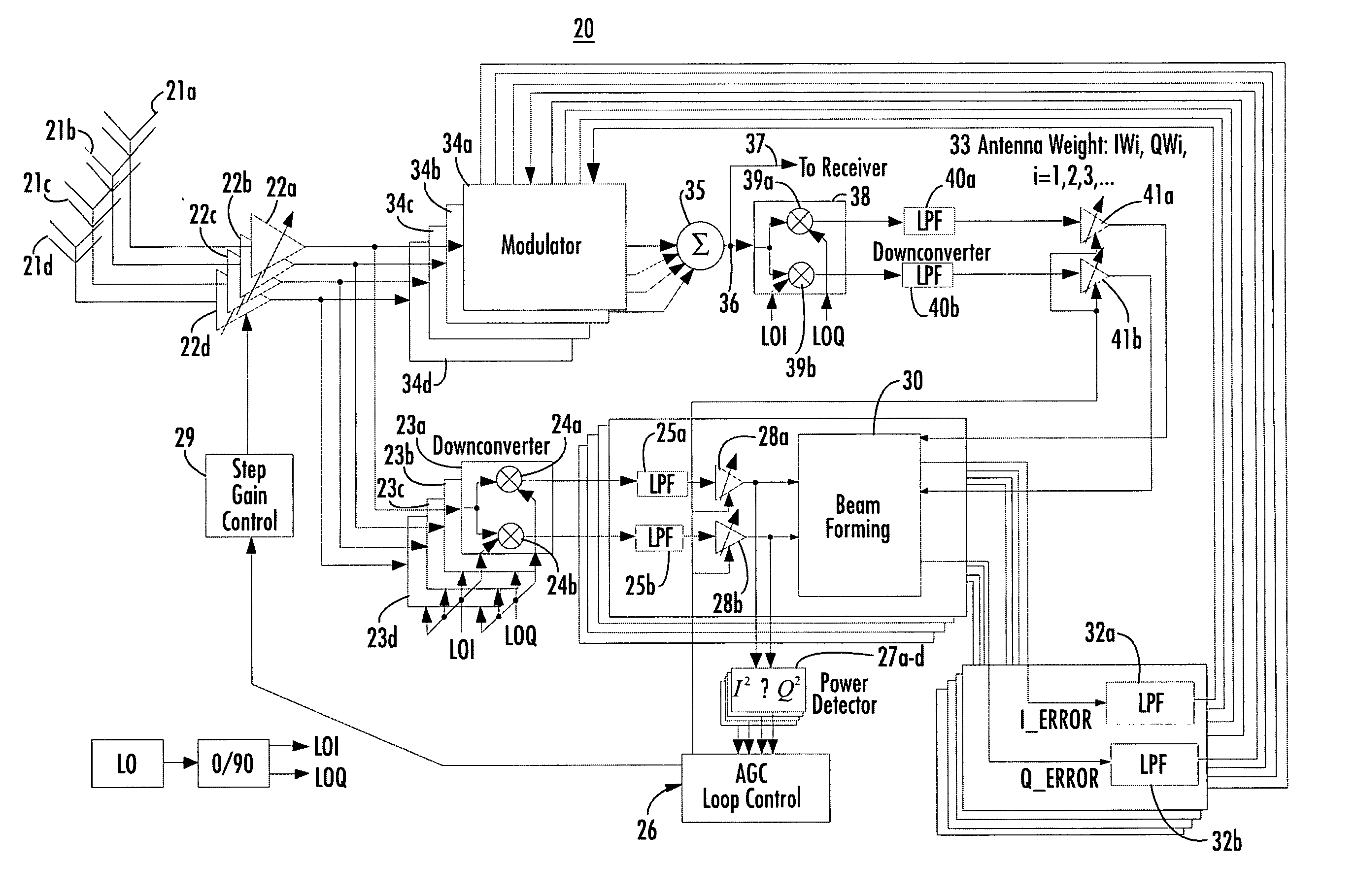
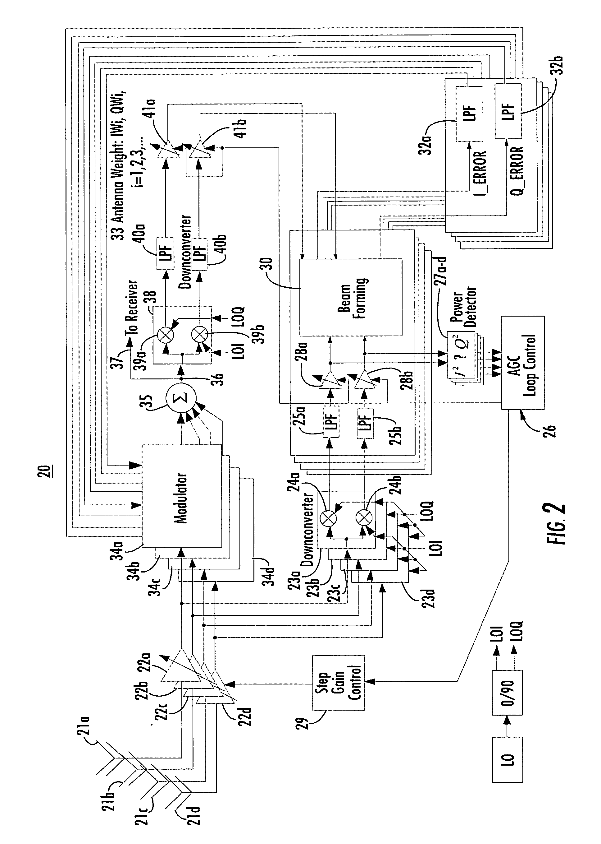
[0055]FIG. 2 is an illustration of wireless receive beam forming system including closed loop implementation of MRC for performing the meth...


PUM


Abstract

The present invention provides a method and system for operating a wireless communication system in which received signals from a plurality of antennas are weighted and combined with a beam forming operation to form an output signal. The beam forming operation determines weights adjusted to increase a desired signal power in the output signal while reducing the power in the output signal of out-of-band components. In an embodiment of the present invention, beam forming operations are performed with maximal ratio combining (MRC). Alternatively, a constant modulus algorithm (CMA) can be used for beam forming operations. In an alternate embodiment, improved interference suppression is performed with a novel algorithm referred to as an interference nulling algorithm (INA). The INA receives an error signal which is 180° out of phase with a combination of the channels for individual antennas, referred to as the SUM channel. The error signal is determined by complex conjugate multiplication of the individual signals and a reference complex signal. It is desirable to simultaneously achieve diversity and combining gain and suppress the adjacent channel by combining the weight generation for MRC and that for INA, as described above, to generate antenna weights similar to those of MMSE combining.

Description

BACKGROUND OF THE INVENTION [0001] 1. Field of the Invention [0002] This invention relates generally to wireless communication systems. More particularly, it relates to a wireless communication system using a plurality of antenna elements with weighting and combining techniques for optimizing antenna diversity and combining gain. [0003] 2. Description of the Related Art [0004] Recently, the market for wireless communications has enjoyed tremendous growth. Wireless technology now reaches or is capable of reaching virtually every location on the face of the earth. Hundreds of millions of people exchange information every day using pagers, cellular telephones and other wireless communication products. [0005] With the appearance of inexpensive, high-performance products based on the IEEE 802.11a / b / g Wireless Fidelity (Wi-Fi) standard, acceptance of wireless local area networks (WLANs) for home, Small Office Home Office (SOHO) and enterprise applications has increased significantly. IEEE...

Claims


Application Information

Patent Timeline
Patent Type & Authority Applications(United States)
IPC IPC(8): H04B7/08H04B1/06H04B7/10H04B17/40
CPCH04B7/0857H04B7/086H04B7/10Y02B60/50Y02D30/70
Inventor WANG, JAMES JUNE-MINGWINTERS, JACKDOONG, MENG CHANGYANG, CHAU CHIN
Owner RENDA TRUST
Why Eureka
Try Eureka