
Electrical cables

Inactive Publication Date: 2006-06-29
SCHLUMBERGER CONVEYANCE & DELIVERY
View PDF15 Cites 27 Cited by
  • Summary
  • Abstract
  • Description
  • Claims
  • Application Information

AI Technical Summary

Benefits of technology

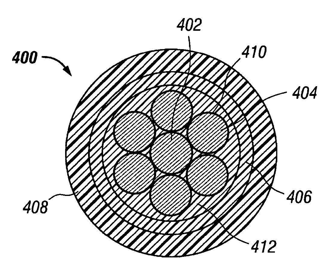
[0010] In one aspect of the invention, an electrical cable is provided. The cable includes an electrical conductor made of a central metallic conductor and a plurality of coated metallic conductors helically positioned around the central metallic conductor, a polymeric protective layer disposed adjacent to the electrical conductor, a first insulating jacket disposed adjacent the polymeric protective layer and having a first relative permittivity. A second insulating jacket disposed adjacent the first insulating jacket and having a second relative permittivity that is less than the first relative permittivity.
[0011] In another aspect of the invention, an electrical cable is provided which includes a plurality of insulated electrical conductors, wherein each insulated electrical conductor includes a central coated metallic conductor and a plurality of coated metallic conductors helically positioned around the central metallic conductor, a polymeric protective layer disposed adjacent the electrical conductor, a first insulating jacket disposed adjacent the polymeric layer wherein the first insulating jacket has a first relative permittivity, and, a second insulating jacket disposed adjacent the first insulating jacket and having a second relative permittivity that is less than the first relative permittivity. The electrical cable further includes an electrically non-conductive jacket surrounding the insulated electrical conductors, an interstitial filler disposed between the jacket and insulated electrical conductors, and a plurality of insulated current return conductors disposed between the jacket and said insulated

Problems solved by technology

Formations generally comprising shale, which may also encapsulate oil-bearing formations, may have porosities much greater than that of sandstone or limestone, but, because the grain size of shale is very small, it may be very difficult to remove the oil or gas trapped therein.
This design may also avoid using the metallic armor as an electrical return conductor, as such configurations may present a hazard to personnel and equipment that inadvertently come into contact with the armor wires during operation of the logging tools.
Further, in some applications, dielectric wireline cables are exposed to significant levels of corrosive chemicals, such as hydrogen sulfide.
The presence of corrosive chemicals, such as hydrogen sulfide, in wells or well fluids can cause significant damage to armor wires and metallic conductors.
The destructive process is principally hydrogen embrittlement, accompanied by chemical attack.
High-strength steels used in armor wires, which have high carbon content and are highly cold-worked, are particularly susceptible to damage by hydrogen sulfide.
Coated conductors have higher resistance that traditional uncoated conductors thereby limiting the ability to transmit power for a given cable diameter.
Coated metallic conductors are prone to having the coating flake off during the manufacture, handling, and use.
The coating flakes tend to mix with the insulation layers or jackets thereby causing localized electric field enhancement which may lead to partial discharge activity or even a reduction in dielectric strength.
This may result in a loss of ability to adequately transmit power.

Method used


Image

  • Electrical cables
  • Electrical cables
  • Electrical cables

Examples


Embodiment Construction

[0023] Illustrative embodiments of the invention are described below. In the interest of clarity, not all features of an actual implementation are described in this specification. It will of course be appreciated that in the development of any such actual embodiment, numerous implementation-specific decisions must be made to achieve the developer's specific goals, such as compliance with system related and business related constraints, which will vary from one implementation to another. Moreover, it will be appreciated that such a development effort might be complex and time consuming but would nevertheless be a routine undertaking for those of ordinary skill in the art having the benefit of this disclosure.

[0024] An electrical voltage applied to an electrical conductor produces an electric field around the conductor. The strength of the electric field varies directly according to the voltage applied to the conductor. When the voltage exceeds a critical value (i.e., the inception v...


PUM


Abstract

An electrical cable is provided which includes a coated electrical conductor, a polymeric protective layer which traps any coating flakes, a first insulating jacket disposed adjacent to the electrical conductor and having a first relative permittivity. A second insulating jacket disposed adjacent to the first insulating jacket and having a second relative permittivity that is less than the first relative permittivity. In another aspect of the present invention, a method is provided for manufacturing a cable that includes providing a coated electrical conductor, extruding a polymeric protective layer over the coated electrical conductor, extruding a first insulating jacket over the protective polymeric layer, and extruding a second insulating jacket thereon. Cables of the invention may further include armor wire layers or even current return conductors.

Description

BACKGROUND OF THE INVENTION [0001] 1. Field of the Invention [0002] This invention relates to a redistributed electric field cable and a method of manufacturing same. In one aspect, the invention relates to a corrosion resistant redistributed electric field cable used with devices to analyze geologic formations adjacent a well before completion and a method of manufacturing same. [0003] 2. Description of the Related Art [0004] Generally, geologic formations within the earth that contain oil and / or petroleum gas have properties that may be linked with the ability of the formations to contain such products. For example, formations that contain oil or petroleum gas have higher electrical resistivity than those that contain water. Formations generally comprising sandstone or limestone may contain oil or petroleum gas. Formations generally comprising shale, which may also encapsulate oil-bearing formations, may have porosities much greater than that of sandstone or limestone, but, becaus...

Claims


Application Information

Patent Timeline
IPC IPC(8): H01B11/02
CPCH01B7/0291H01B7/046H01B7/2806
Inventor VARKEY, JOSEPH P.KIM, BYONG JUNWIJNBERG, WILLEM A.ARIF, FAISALSINGH, ANILARNAUD, JEFFREYNGUYEN, JOHN CUONG
Owner SCHLUMBERGER CONVEYANCE & DELIVERY
Learn More