Inner drum exposure apparatus

Inactive Publication Date: 2006-06-29
FUJIFILM CORP +1
View PDF2 Cites 9 Cited by
  • Summary
  • Abstract
  • Description
  • Claims
  • Application Information

AI Technical Summary

Benefits of technology

[0029] In accordance with the structure mentioned above, it is possible to increase a quality of recording pixels by dividing each of the light beams such that the focused spots are overlapped adjacently approximately at the uniform light intensity in the sub-scanning direction, while using the quarter wave plate and the uniaxial crystal, thereby forming each of the light beams as a spot shape which is closer to a rectangular shape with respect to the sub-scanning direction, and is in a focu

Problems solved by technology

Accordingly, it is necessary to limit a rotational speed of the spinner rotation axis apparatus to a low speed, and there is generated a problem that

Method used


Image

  • Inner drum exposure apparatus
  • Inner drum exposure apparatus
  • Inner drum exposure apparatus

Examples


first embodiment

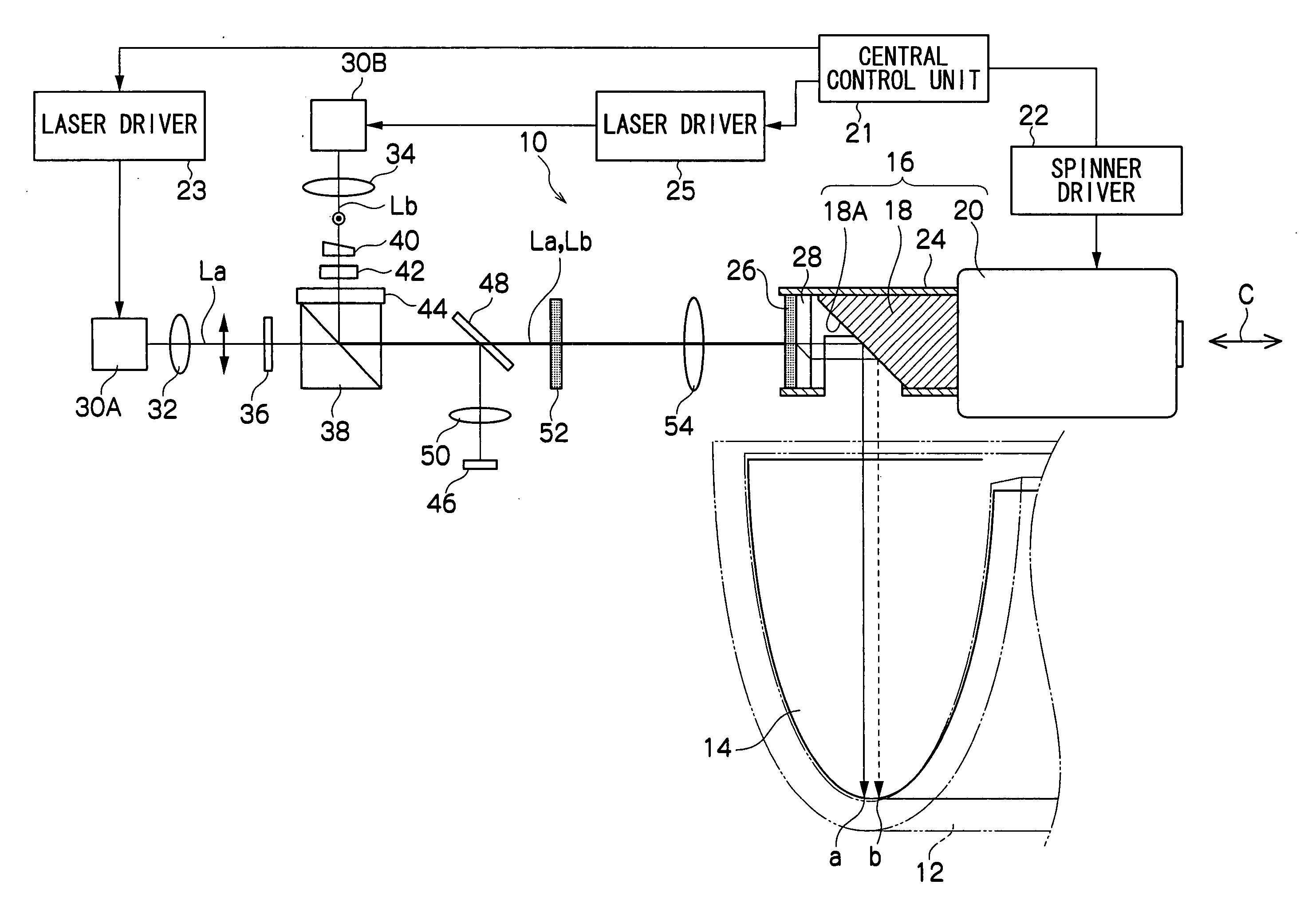
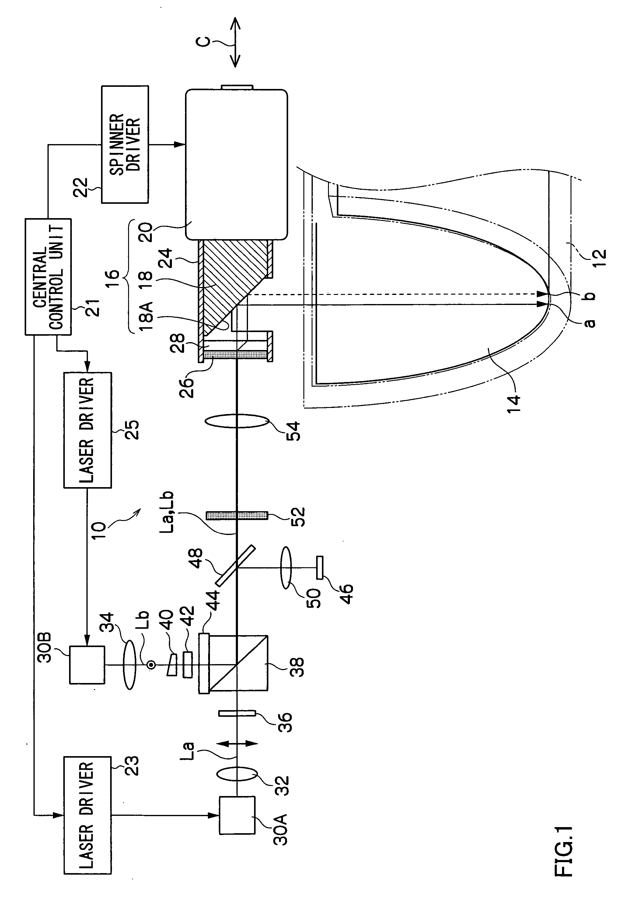
[0040] A description will be given of a first embodiment in accordance with an inner drum exposure apparatus of the present invention with reference to FIG. 1. As shown in the schematic block diagram in FIG. 1, an inner drum exposure apparatus 10 is structured by providing a support body 12 having a circular arc inner peripheral surface shape (a shape constituting a part of a cylindrical inner peripheral surface) as a base body, and a recording medium 14 (a photopolymer type, normal PS type or silver salt type photosensitive material or the like) is supported along an inner peripheral surface of the support body 12.

[0041] In this case, in the inner drum exposure apparatus 10, an unrecorded recording medium 14 is supplied by a supply and discharge apparatus (not shown) of the recording medium 14, an exposure process is executed after the recording medium 14 is securely brought into close contact with an inner peripheral surface of the support body 12 so as to be engaged and attached ...

second embodiment

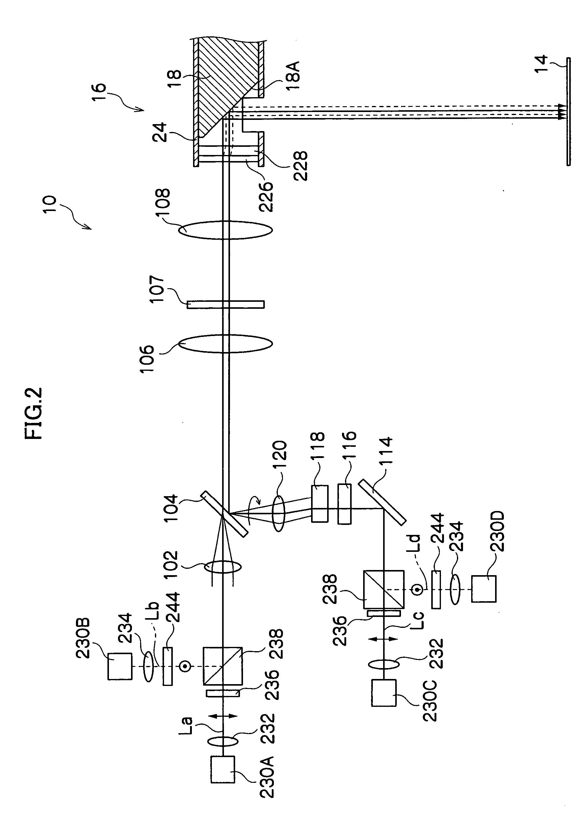
[0099] In the inner drum exposure apparatus 10 in accordance with the second embodiment, the structure is made such that a high speed exposure process can be executed by switching the resolution while maintaining the beam division width in the initially set sub-scanning direction, in a four multi-beam exposure system. Accordingly, in the inner drum exposure apparatus 10, two sets of two laser beams, totally four laser beams La, Lb, Lc and Ld emitted by being divided from the optical element 228 of the uniaxial crystal are reflected by the spinner mirror apparatus 16 serving as the light deflector, and four laser beams La, Lb, Lc and Ld are focused and exposed at respective positions mutually separated at a predetermined distance corresponding to one recording pixel in the sub-scanning direction on the scanning surface of the recording medium 14.

[0100] Further, the inner drum exposure apparatus 10 is structured such that scanning unevenness appearing on the image obtained by focusing...


PUM


Abstract

An exposure process is executed by multi-beams divided by polarizing and combining laser beams (La, Lb) modulated based on an image signal so as to be emitted by a light source side optical system by using a polarized light beam splitter, and by converting the laser beams (La, Lb) emitted as right circular polarized light and left circular polarized light into mutually orthogonal linear polarized light by using a quarter wave plate arranged on a light path of a scanning portion, and thereafter transmitting through an optical element of uniaxial crystal. An appropriate image can be formed by setting a division width of beam spots on a scanning surface set by the optical element of uniaxial crystal such that scanning unevenness of an image formed on a scanning surface is within an allowable range even when changing resolution of the inner drum exposure apparatus.

Description

CROSS-REFERENCE TO RELATED APPLICATION [0001] This application claims priority under 35 USC 119 from Japanese Patent Application No. 2004-381976, the disclosure of which is incorporated by reference herein. BACKGROUND OF THE INVENTION [0002] 1. Field of the Invention [0003] The present invention relates to an inner drum exposure apparatus (an inner surface scanning type light beam scanning exposure apparatus) for scanning a photosensitive surface arranged in an inner surface of a cylindrical drum by a scanning optical system of a light beam so as to executed an exposure process. [0004] 2. Description of the Related Art [0005] Widely used is an inner drum exposure apparatus (an inner surface scanning type light beam scanning exposure apparatus) executing a scanning exposure process by introducing a light beam such as a laser beam or the like to a photosensitive surface of a recording medium arranged on an inner peripheral surface of a cylindrical drum by a light deflector. The record...

Claims


Application Information

Patent Timeline
IPC IPC(8): G02B26/08
CPCG02B26/123G02B27/283H04N1/0607
Inventor MIYAGAWA, ICHIROU
Owner FUJIFILM CORP
Why Eureka
Try Eureka