
Method of calibrating light delivery systems, light delivery systems and radiometer for use therewith

a technology of light delivery system and radiometer, which is applied in the direction of photometry, electrostatic spraying apparatus, radiation therapy, etc., can solve the problems of long exposure time needed to properly cure adhesive, and undesirable differences between output intensity levels of different light curing systems

Active Publication Date: 2006-06-29
EXCELITAS CANADA +1
View PDF9 Cites 15 Cited by
  • Summary
  • Abstract
  • Description
  • Claims
  • Application Information

AI Technical Summary

Benefits of technology

[0044] The intensity control unit may function as a shutter and may compensate for shutter opening and closing delays when determining exposure times.

Problems solved by technology

As the light source degrades, so will the amount of light energy being delivered to cure the adhesive and therefore a longer exposure time is needed to properly cure the adhesive.
Calibration of these multiple radiometers is not only time-consuming but also may lead to undesirable differences between the output intensity levels.
Different rates of degradation of the light sources and transmission losses of the light guides, as well as different rates of drift of the radiometers, may lead to undesirable differences between output intensity levels of the different light curing systems.
The problem is compounded where several light curing systems are preset to the same output intensity or irradiance setting.
As the light curing systems degrade differentially, these settings may no longer be the same and may require re-calibration, typically at least once per week and possibly every day.

Method used


Image

  • Method of calibrating light delivery systems, light delivery systems and radiometer for use therewith
  • Method of calibrating light delivery systems, light delivery systems and radiometer for use therewith
  • Method of calibrating light delivery systems, light delivery systems and radiometer for use therewith

Examples


Embodiment Construction

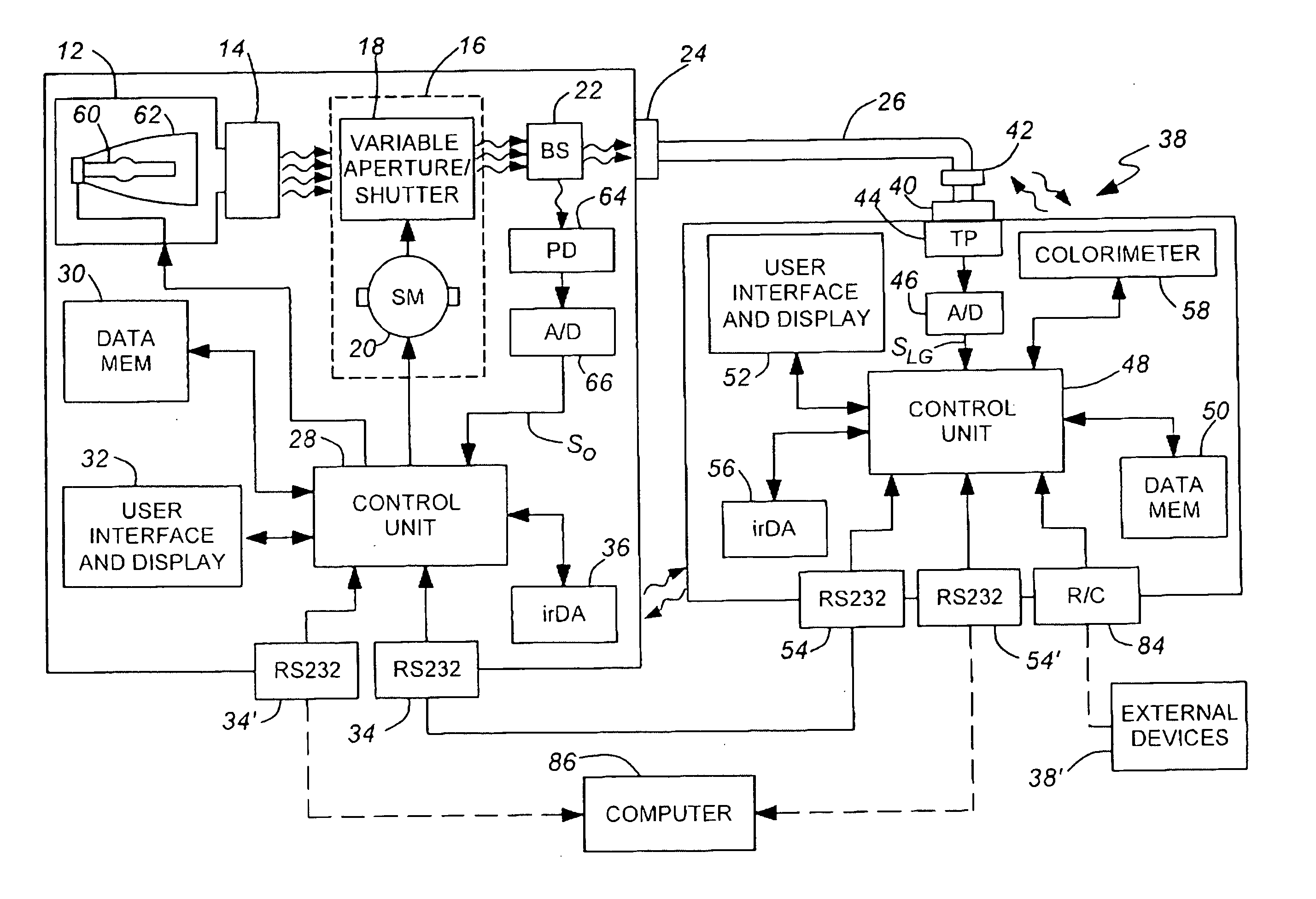
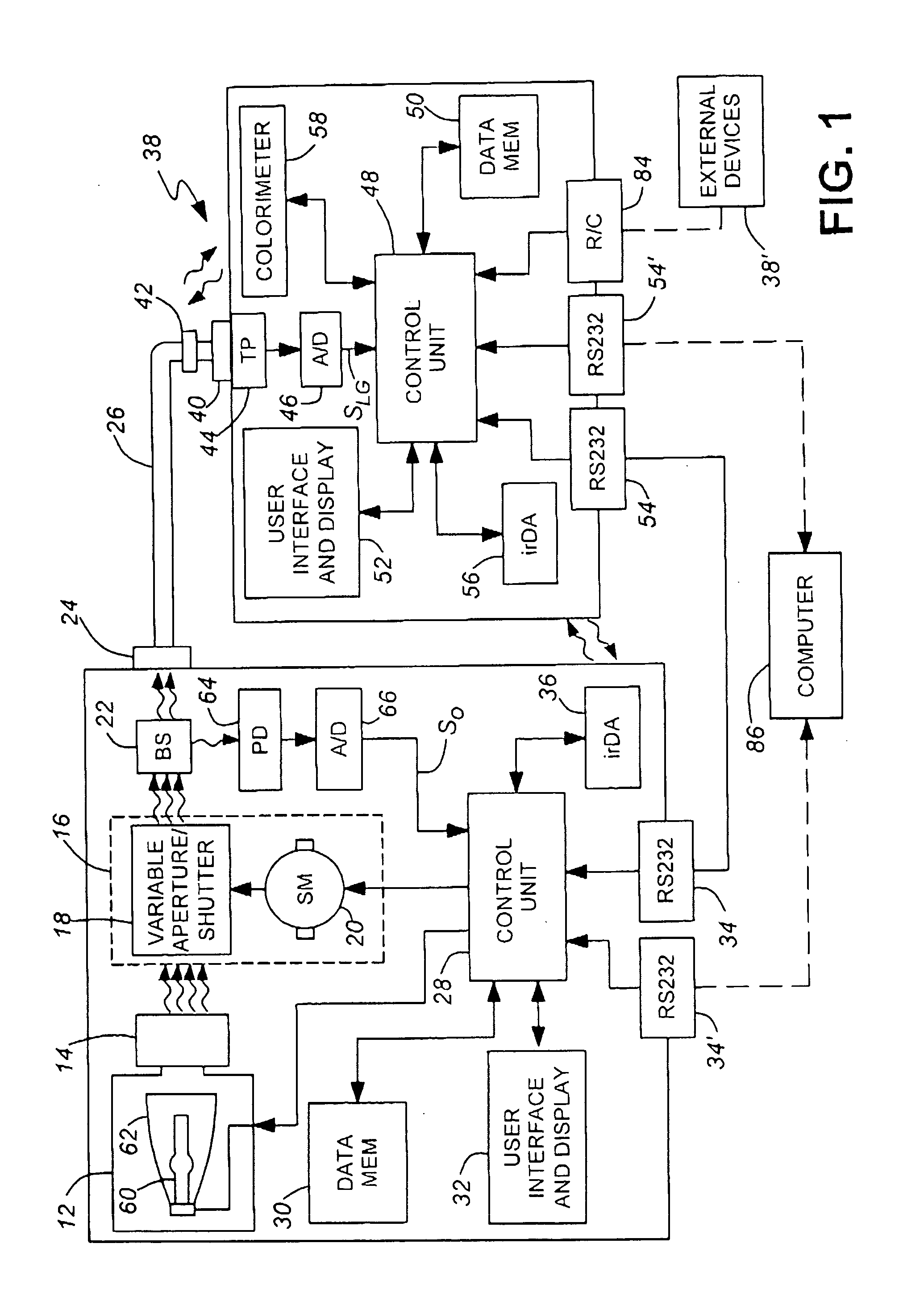
[0050]FIG. 1 illustrates a light delivery system comprising a light delivery device 10, for example a spot curing device, which, typically, is one of a set of similar such light delivery devices, perhaps disposed along the same production line. Thus, the light delivery device 10 comprises a light source unit 12, a bandpass filter 14, an intensity control module 16 comprising a variable aperture unit 18 and stepper motor 20, a beam splitter 22 and an output port 24 to which, in use, a light delivery means 26, specifically a light guide, can be connected. The light source unit 12 comprises a lamp 60, typically an arc lamp, in a reflective lamp housing 62.

[0051] The stepper motor 20 is controlled by a control unit 28 which comprises one or more processors and an associated data memory unit 30 and is programmed (e.g. firmware) to control the operation of the light delivery device 10. The control unit 28 is coupled to a user interface and display unit 32, whereby a user can input comman...


PUM

PropertyMeasurementUnit
irradianceaaaaaaaaaa
irradiance levelaaaaaaaaaa
diameteraaaaaaaaaa

Abstract

A light delivery device (10) having a light source (12) and a variable aperture unit (18) is temporarily connected by a light guide (24; 24, 26) to a radiometer (38) for detecting irradiance of the delivered light. The light delivery device has a memory (30) for storing irradiance levels. The light delivery device is calibrated by adjusting the aperture to each of a series of predetermined settings, obtaining from the radiometer a corresponding series of delivered light irradiance levels measured thereby, storing the irradiance levels and aperture settings in memory, and applying a best fit algorithm to the irradiance measurements and aperture settings. Thereafter, a desired irradiance level can be set by selecting the best fit aperture setting. Output intensity levels may be measured at the same time as the irradiance levels and used to compensate for light source degradation when setting a desired irradiance level.

Description

CROSS REFERENCE TO RELATED APPLICATION [0001] This application claims priority from U.S. Provisional patent application No. 60 / 638,344 filed Dec. 23, 2004, the entire contents of which are incorporated herein by reference.DESCRIPTION [0002] 1. Technical Field [0003] The invention relates to methods of calibrating light delivery systems, to the light delivery systems themselves and to radiometers for use therewith and is especially, but not exclusively, applicable to light delivery systems for curing photosensitive materials. [0004] 2. Background Art [0005] As discussed in the background section of U.S. Pat. No. 5,521,392 (Kennedy et al.), commonly owned with the present invention, there are numerous substances which are sensitive to light energy. The substances of interest generally fall into two classes. The first class comprises substances which undergo polymerization in response to applied light energy. The second class comprises substances which produce a “singlet oxidation mole...

Claims


Application Information

Patent Timeline
Patent Type & Authority Applications(United States)
IPC IPC(8): G02B26/02G02F1/03
CPCA61N5/062G01J1/32G01J1/42G01J2001/4247
Inventor KAYSER, ROYRICE, GRAEMEZHANG, XUMING
Owner EXCELITAS CANADA
Learn More