High voltage pulse generator

a generator and high-voltage technology, applied in the direction of pulse generators, pulse techniques, pulse trains, etc., can solve the problems of limited high-end applications, state approaches, and difficult realization

Active Publication Date: 2006-06-29
EXCELITAS TECH
View PDF3 Cites 43 Cited by
  • Summary
  • Abstract
  • Description
  • Claims
  • Application Information

AI Technical Summary

Benefits of technology

[0006] The present invention is apparatus for, and method of, generating a high voltage pulse. The pulse generator includes an even number of capacitor charging circuits, each comprising an LC inversion Marx generator with two or more capacitors and a switch to control the discharge of the capacitors. A cell inverter transformer is provided for each charging circuit. The primary winding of each cell inverter transformer is connected to the ac output of a power supply such as a series-resonant inverter. The secondary winding of each cell inverter transformer is connected via rectifying means to the charging circuit to charge the capacitors. One-half of the cell inverter transformers have their primary windings connected to the ac output of the power supply in inverted phase to that of the remaining cell inverter transformers.

Problems solved by technology

Over the past several years, all-solid-state approaches based on magnetic pulse compression have emerged, but have generally been restricted to high end applications because of cost and a pervasive belief that such designs are difficult to realize.

Method used


Image

  • High voltage pulse generator
  • High voltage pulse generator
  • High voltage pulse generator

Examples


Embodiment Construction

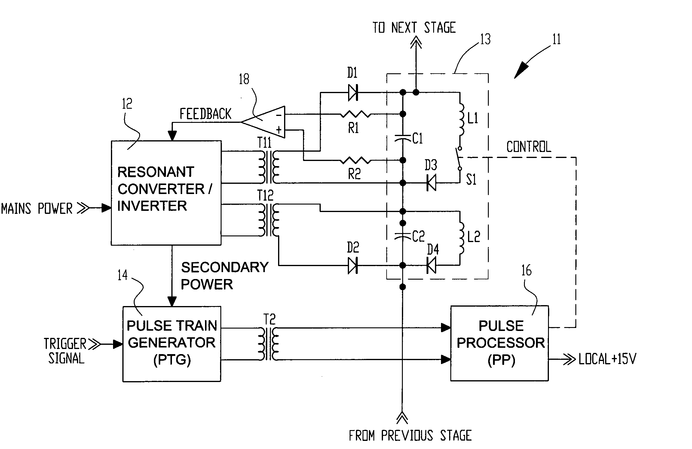
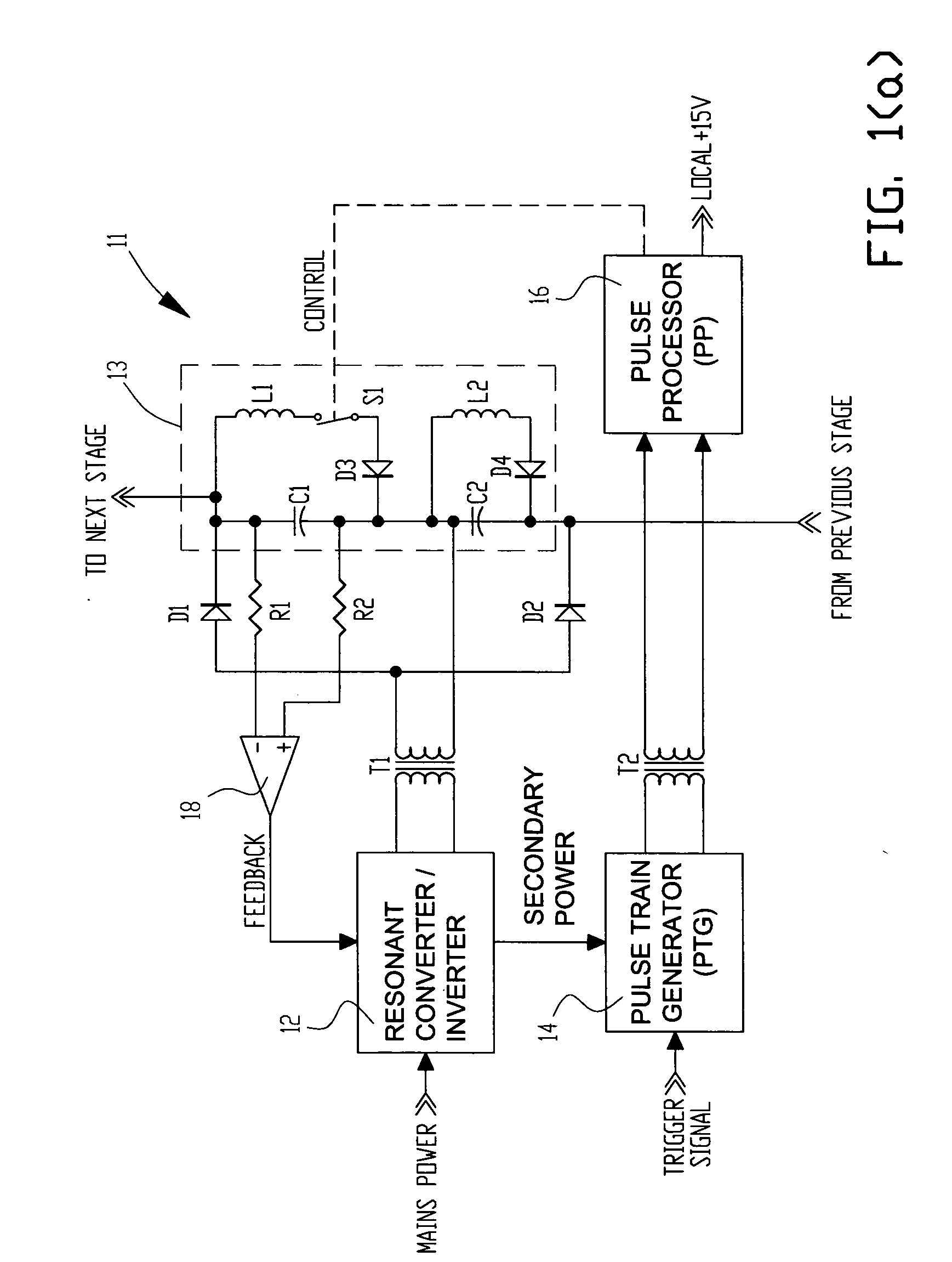
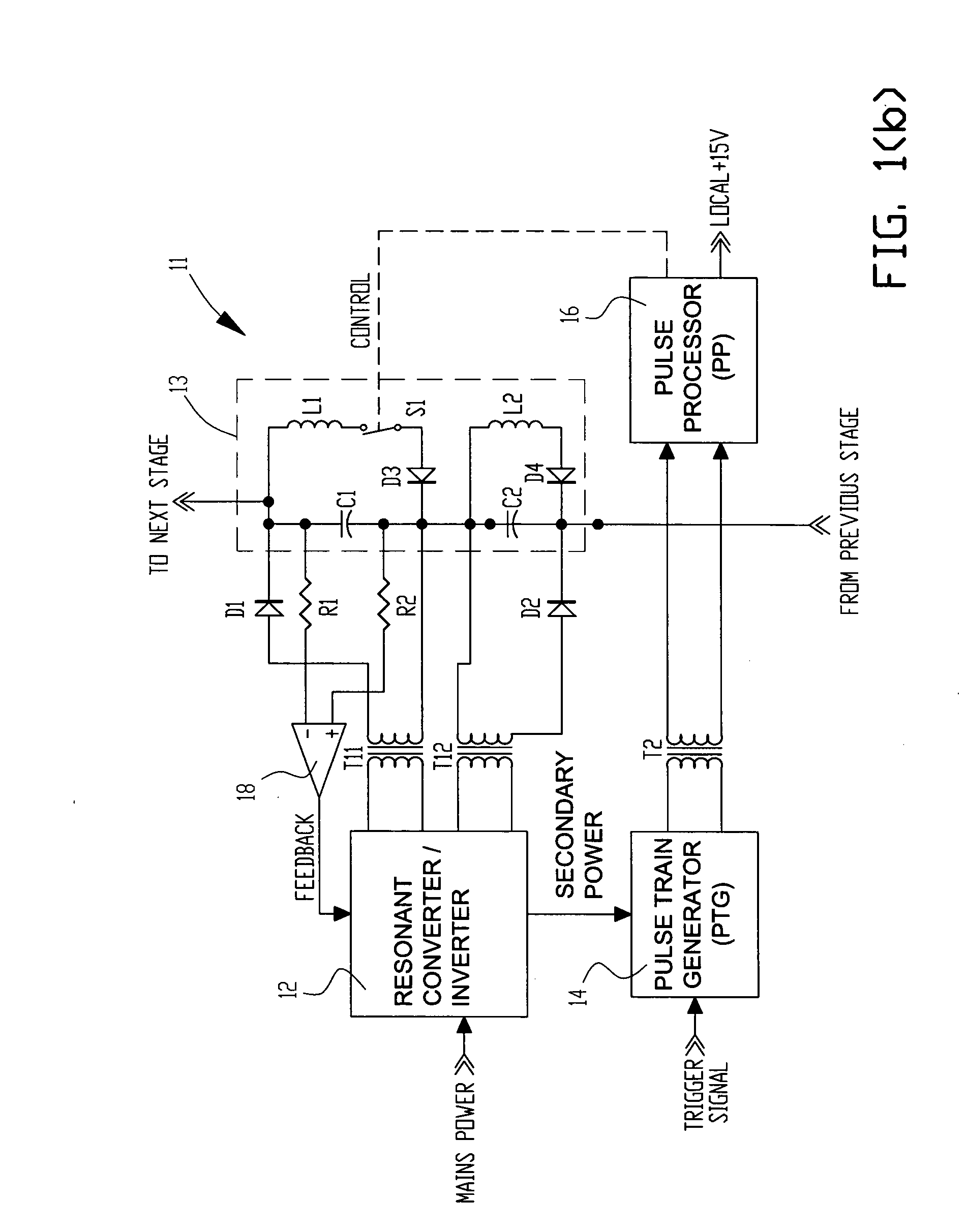
[0028] Referring now to the drawings, wherein like numerals indicate like elements, there is shown in the figures one example of the high voltage pulse generator of the present invention. The capacitor charging circuit of the pulse generator utilizes multiple charging cells or stages, each of which uses a Marx generator wherein two or more capacitors are charged in parallel and discharged in series. The utilized Marx generator is specifically of the type known as an “LC inversion Marx generator” or “LC vector inversion circuit.” As illustrated in FIG. 1(a) a typical single cell (or stage) of charging circuit 11 utilizes a Marx cell 13 comprising capacitors C1 and C2, inductors L1 and L2, diodes D3 and D4, and switch S1. Inductor L1 is in parallel with capacitor C1, with diode D3 and switch S1 inserted between the inductor and capacitor as shown in FIG. 1(a); inductor L2 is in parallel with capacitor C2, with diode D4 inserted between the inductor and capacitor as shown in FIG. 1(a)....


PUM


Abstract

A high voltage pulse generator utilizes an even number of Marx cells using L-C inversion topology. Each Marx cell is associated with an individual inverter transformer having a primary winding connected to the output of an ac power supply such as a series resonant inverter. The secondary of each inverter transformer is half-wave rectified to charge the energy storage capacitors in each Marx cell. A distributed voltage sensing scheme can be provided for accurate feedback to the inverter's controller. An inductive element can be used to achieve a magnetic diode effect in the L-C inversion circuit to reduce component stress and improve efficiency. A transformer-coupled floating gate drive circuit is used to provide local power conditioning and trigger timing for discharge of the energy storage capacitors.

Description

CROSS REFERENCE TO RELATED APPLICATIONS [0001] Not applicable. FIELD OF THE INVENTION [0002] The present invention relates to high voltage pulse generators for use with pulsed loads in applications such as excimer lasers. BACKGROUND OF THE INVENTION [0003] Various electrical devices, such as excimer lasers, require a fast rise, high voltage, high current electrical discharge of an energy pulse for their operation. Such a pulse is applied to the laser cavity in a manner that atomically excites the laser gas to metastable quantum states. By proper laser design, these states collapse in unison to produce the desired optical output pulse. [0004] The generation of the energy pulse has been accomplished by using at least two power electronics modules, namely: (1) a high voltage power supply (HVPS) that provides a current-controlled output used to charge external energy storage capacitors over a relatively long period of time; and (2) a power modulator that draws upon the energy storage ca...

Claims


Application Information

Patent Timeline
Patent Type & Authority Applications(United States)
IPC IPC(8): H02M3/335H02M7/48
CPCH02M3/3376H02M2001/009Y02B70/1433H02M3/07H02M3/285H02M1/009Y02B70/10
Inventor OICLES, JEFFREY ALANJOHNS, DAVID M.
Owner EXCELITAS TECH
Why Eureka
Try Eureka