Optical information reproduction device

a technology of optical information and reproduction device, which is applied in the direction of optical recording/reproducing/erasing methods, instruments, optical beam sources, etc., can solve the problems of inability to reproduce, adversely affect the reproduction of information, and loss of ligh

Inactive Publication Date: 2006-06-29
PANASONIC CORP
View PDF9 Cites 20 Cited by
  • Summary
  • Abstract
  • Description
  • Claims
  • Application Information

AI Technical Summary

Benefits of technology

[0010] The optical information reproduction device of the present invention comprises an information recording medium that includes a recording unit capable of recording information three-dimensionally and provided with a track having a specific track pitch, with which information is recorded by forming a plurality of recording marks along the track of the recording unit by a mark length recording method, and when the track direction of the recording marks is assumed to be their longitudinal direction and the direction perpendicular to the track direction is assumed to be their lateral direction, for recording marks located substantially in the same plane, the total area of elongated recording marks, whose longitudinal length is greater than their lateral length, is greater than the total area of recording marks having other than elongated shapes; a first light source for emitting reproduction light having a wavelength λ1; an objective lens for focusing the reproduction light emitted from the first light source on the recording unit of the information recording medium; and a first photodetector for detecting a reproduction signal from the reflected light from the recording unit, wherein the information recording medium has a track pitch of no more than 1.3 times the wavelength λ1 of the reproduction light, and when focused on the information recording medium, the reproduction light includes as its main component a polarized light component that is polarized perpendicular to the track direction of the information recording medium. The phrase “includes as its main component a polarized light component that is polarized perpendicular to the track direction” means that the amplitude of the polarized light component that is polarized perpendicular to the track direction is greater than that of other polarized light components. The “track” referred to here includes, in addition to a configuration in which a track groove is formed, a configuration in which no track groove is formed and no recording marks are formed, and instead a track hypothetically is assumed to be a path over which recording marks are recorded.

Problems solved by technology

However, with the above-mentioned conventional device, in the reproduction of information that has been recorded to a target recording layer (such as the recording layer 101c shown in FIG. 7), light is lost through diffraction loss of the converged light 107 due to the recording pits formed in the recording layers 101a and 101b located in front of the target layer (on the incident light side, and the objective lens 106 side), and this adversely affects the reproduction of information.
Specifically, when there are many recording layers in front of the target layer, the light is attenuated by the time it reaches the target recording layer, making reproduction impossible, so it has been difficult to reproduce information from large-capacity information recording media having many layers.

Method used


Image

  • Optical information reproduction device
  • Optical information reproduction device
  • Optical information reproduction device

Examples


embodiment 1

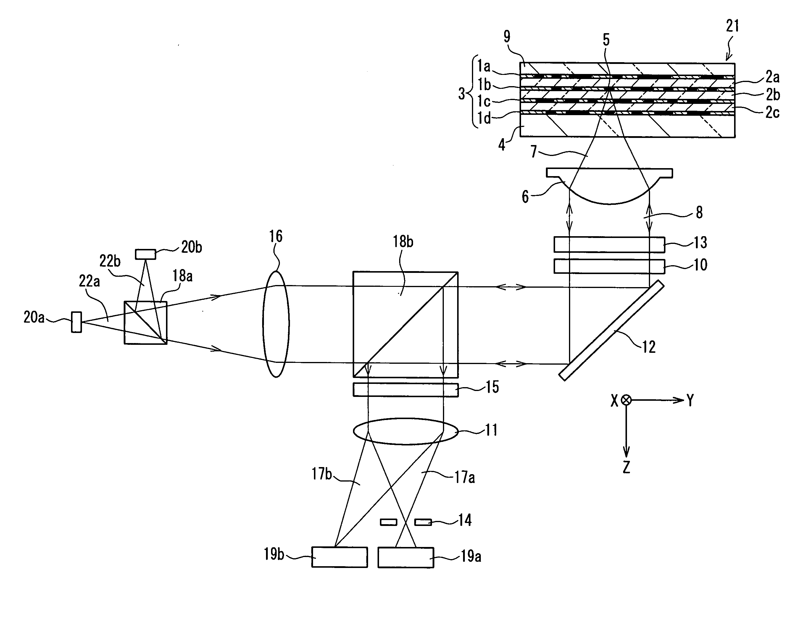
[0027] The optical information reproduction device of Embodiment 1 of the present invention will be described in detail with reference to FIGS. 1 and 2. Since the optical information reproduction device in this embodiment is equipped with a recording function as well as a reproduction function, it will be referred to below as an optical information recording and reproduction device.

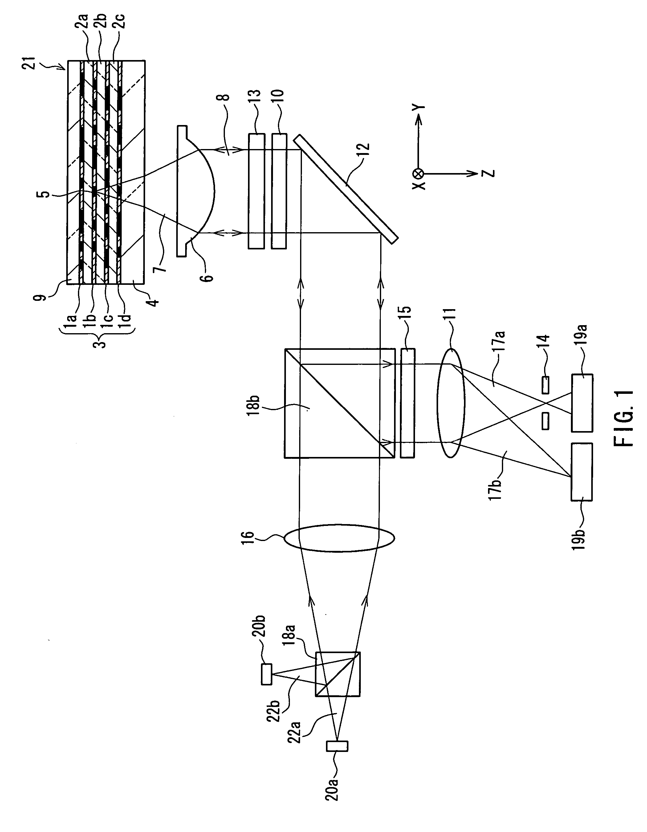
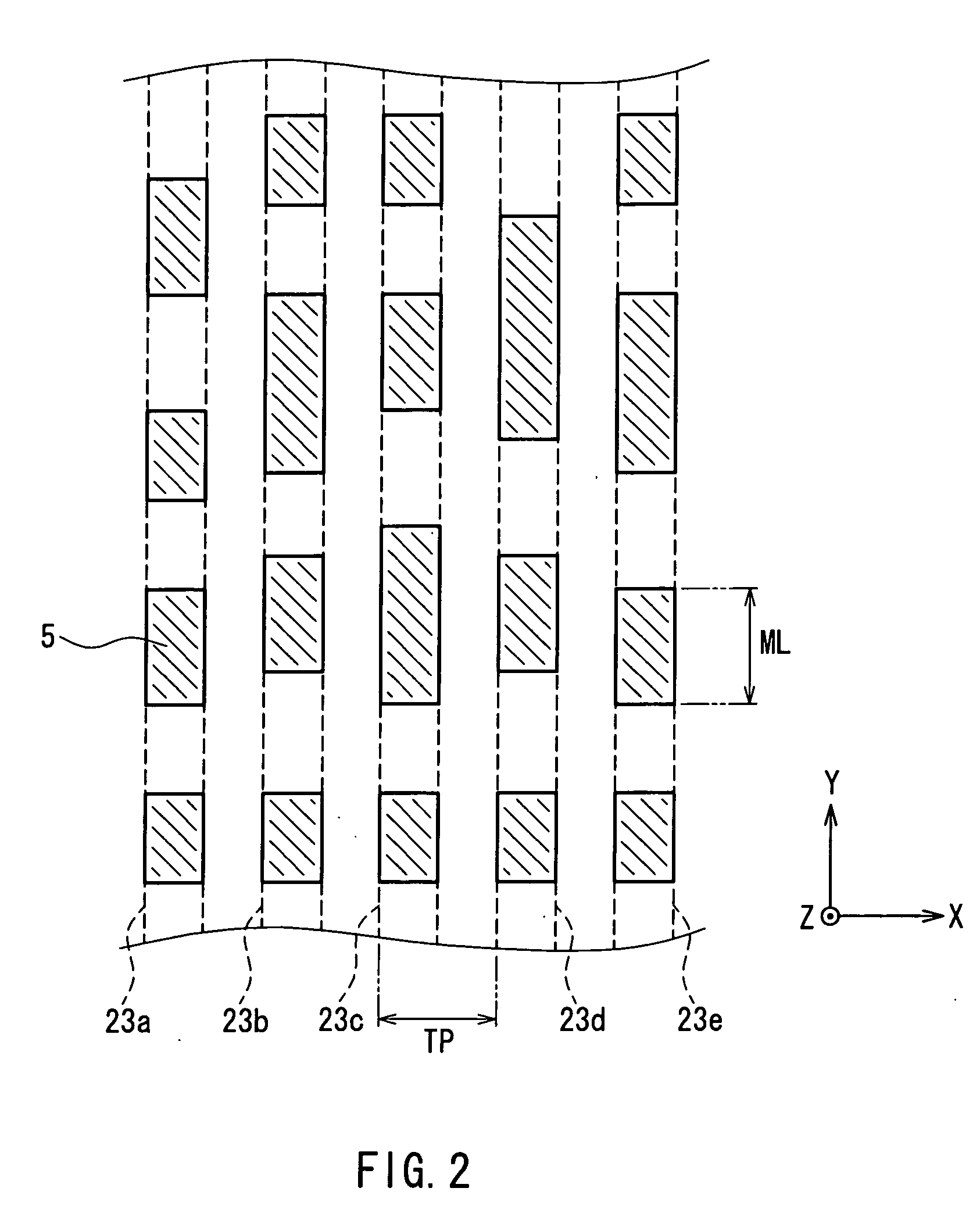
[0028]FIG. 1 is a simplified diagram illustrating the basic constitution of an embodiment of the optical information reproduction device of the present invention, and how light is conveyed. FIG. 2 is a simplified diagram illustrating the recording marks formed on an information recording medium included in this optical information recording and reproduction device.

[0029] The optical information recording and reproduction device of this embodiment is provided with two different light sources: a recording light source (second light source) 20a and a reproduction light source (first light source) 20b. The ...

embodiment 2

[0051] The optical information recording and reproduction device in Embodiment 2 of the present invention will now be described through reference to FIG. 6, focusing on those points that differ from the optical information recording and reproduction device described in Embodiment 1.

[0052]FIG. 6 is a simplified diagram illustrating the basic constitution of the optical information reproduction device in this embodiment, and how light is conveyed.

[0053] The optical information recording and reproduction device of this embodiment comprises a light source 24 that emits light 25 as the recording light or the reproduction light, the objective lens 6 for focusing light 25 emitted from the light source 24 on any of the plurality of recording layers 1a to 1d included in the information recording medium 21, and the first photodetector 19a and a second photodetector 19b for detecting the reflected light 17a and 17b from the information recording medium 21. Further, the collimator lens 16, a ...


PUM

PropertyMeasurementUnit
wavelengthaaaaaaaaaa
sizeaaaaaaaaaa

Abstract

An information recording medium (21) of the optical information reproduction device of the present invention includes a recording unit (3) capable of recording information three-dimensionally and provided with a track, and information is recorded by forming a plurality of recording marks along the track of the recording unit by a mark length recording method. When the track direction of the recording marks is assumed to be their longitudinal direction and the direction perpendicular to the track direction is assumed to be their lateral direction, with the present invention, for recording marks located substantially in the same plane, the total area of elongated recording marks, whose longitudinal length is greater than their lateral length, is greater than the total area of recording marks having other than elongated shapes. The optical information reproduction device of the present invention includes a first light source (20a) for emitting a reproduction light (22b) having a wavelength λ1, an objective lens (6) for focusing the reproduction light on the recording unit, and a first photodetector (19a) for detecting a reproduction signal from the reflected light from the recording unit. The focused reproduction light includes as its main component a polarized light component that is polarized perpendicular to the track direction. Also, the recording unit has a track pitch of no more than 1.3 times the wavelength λ1 of the reproduction light.

Description

TECHNICAL FIELD [0001] The present invention relates to an optical information reproduction device for reproducing information from an information recording medium with which information can be recorded three-dimensionally. BACKGROUND ART [0002] An optical information reproduction device is a device that reproduces information that has been recorded on an information recording medium such as a CD (compact disk), DVD (digital versatile disk), or other such optical disk, an optical card memory, or the like. There are also devices that further comprise a function of recording information onto such information recording media (hereinafter optical information reproduction devices that also comprise a recording function will sometimes be referred to as optical information recording and reproduction devices). [0003] Information recording media with a multilayer structure, in which a plurality of recording layers are stacked over one another, have been provided as information recording medi...

Claims


Application Information

Patent Timeline
Patent Type & Authority Applications(United States)
IPC IPC(8): G11B7/00G11B7/013G11B7/125G11B7/135G11B7/24G11B7/24038G11B7/24085
CPCB82Y10/00G11B7/00452G11B7/00454G11B7/00455G11B7/1275G11B7/1365G11B7/1381G11B7/24038G11B7/24085G11B2007/0013G11B7/005
Inventor SHIONO, TERUHIRONISHINO, SEIJIITOH, TATSUO
Owner PANASONIC CORP
Why Eureka
Try Eureka