Exhaust gas purifying catalyst

Active Publication Date: 2006-06-29
CATALER CORP
View PDF4 Cites 8 Cited by
  • Summary
  • Abstract
  • Description
  • Claims
  • Application Information

AI Technical Summary

Benefits of technology

[0016] A length of the area A along the passage of exhaust gas is preferably 10-50%, is more preferably 30-50%, and is further more preferably 40-50%, of the entire length of the passage. When the passage is formed by two or more substrates, the entire length of the passage is obtained by adding the lengths of the respective through holes along the exhaust gas flow. By defining the proportion of the length of the area A along the passage to the entire length of the passage, further improvements can be achieved in the warm-up performance and the durability.
[0017] A proportion of a weight of the precious metal contained

Problems solved by technology

However, conventional exhaust gas purifying catalysts can

Method used


Image

  • Exhaust gas purifying catalyst
  • Exhaust gas purifying catalyst
  • Exhaust gas purifying catalyst

Examples


embodiment 1

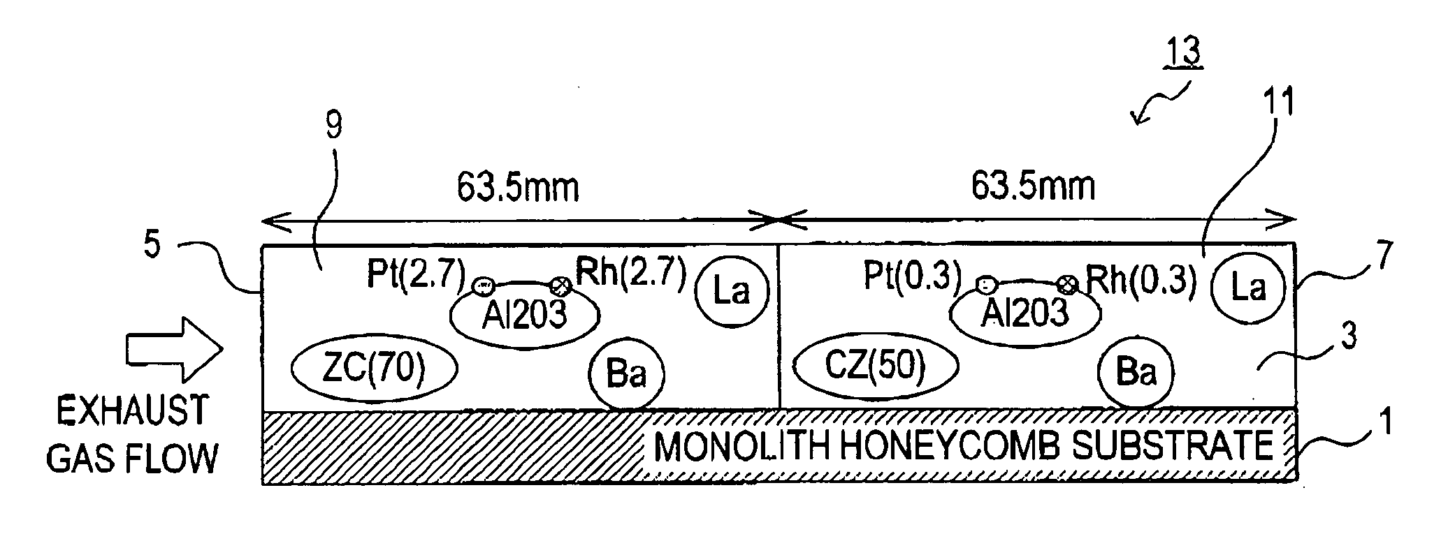
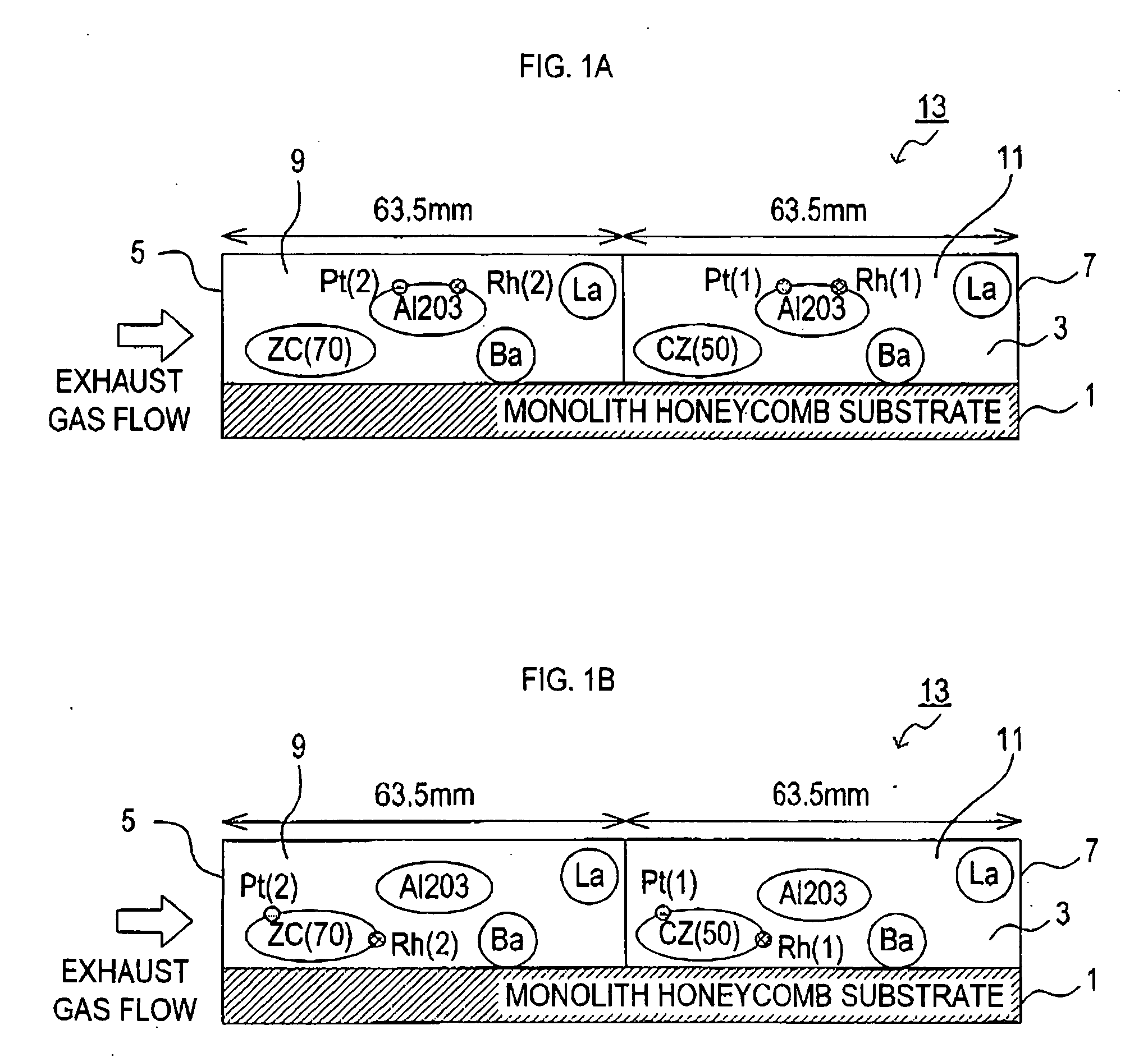
[0030] A honeycomb substrate made of cordurite is employed as a substrate 1. As shown in FIGS. 1A and 1B, the substrate 1, includes a through hole 3 extending in an axial direction and having a constant cross-sectional area. The entire length of the through hole 3 is 127 mm. In FIGS. 1A and 1B, a left end and a right end of the through hole 3 are an entrance end 5 and an exit end 7, respectively.

[0031] Exhaust gas enters the through hole 3 from the entrance end 5, passes through the through hole 3, and exits from the exit end 7. Accordingly, the though hole 3 shown in FIGS. 1A and 1B constitutes a passage of exhaust gas, in which the flow direction of exhaust gas is in a left to right direction. Although only one through hole 3 is indicated in FIGS. 1A and 1B, there actually are multiple through holes 3 formed in parallel with one another.

[0032] First, below listed components are mixed and dried to prepare a carrier powder H1.

[0033] (Carrier Powder H1) [0034] activated alumina: 4...

embodiment 2

[0061] Although an exhaust gas purifying catalyst 13 in Embodiment 2 is produced basically in the same manner as in Embodiment 1, there are some differences. Accordingly, a description will now be made mainly with respect to the differences.

[0062] In Embodiment 2, a carrier powder H3 as described below is prepared in place of the carrier powder H1.

[0063] (Carrier Powder H3) [0064] powder of a ZrCe mixed oxide (the oxide equivalent weight of Zr is 70 wt % of the oxide equivalent weight of Zr and Ce contained in the ZrCe mixed oxide): 50 g [0065] Pt nitrate solution: an amount containing 2 g of metal [0066] Rh nitrate solution: an amount containing 2 g of metal

[0067] A slurry S3 as described below is used in place of the slurry 1 in order to form the upstream side catalyst coating layer 9.

[0068] (Slurry S3) [0069] the carrier powder H2: 54 g [0070] activated alumina: 47 g [0071] Ba sulfate powder: 10 g [0072] La carbonate: 5 g [0073] alumina hydrate: equivalent to 3 g of Al2O3 [00...

embodiment 3

[0076] Although an exhaust gas purifying catalyst 13 in Embodiment 3 is produced basically in the same manner as in Embodiment 1, there are some differences. Accordingly, a description will be made below mainly with respect to the differences.

[0077] In Embodiment 3, a slurry S4 as described below is used in place of the slurry S1 in order to form the upstream side catalyst coating layer 9.

[0078] (Slurry S4) [0079] the carrier powder H1: 51 g [0080] powder of a Zr oxide: 50 g [0081] Ba sulfate powder: 10 g [0082] La carbonate: 5 g [0083] alumina hydrate: equivalent to 3 g of Al2O3 [0084] water: an appropriate amount

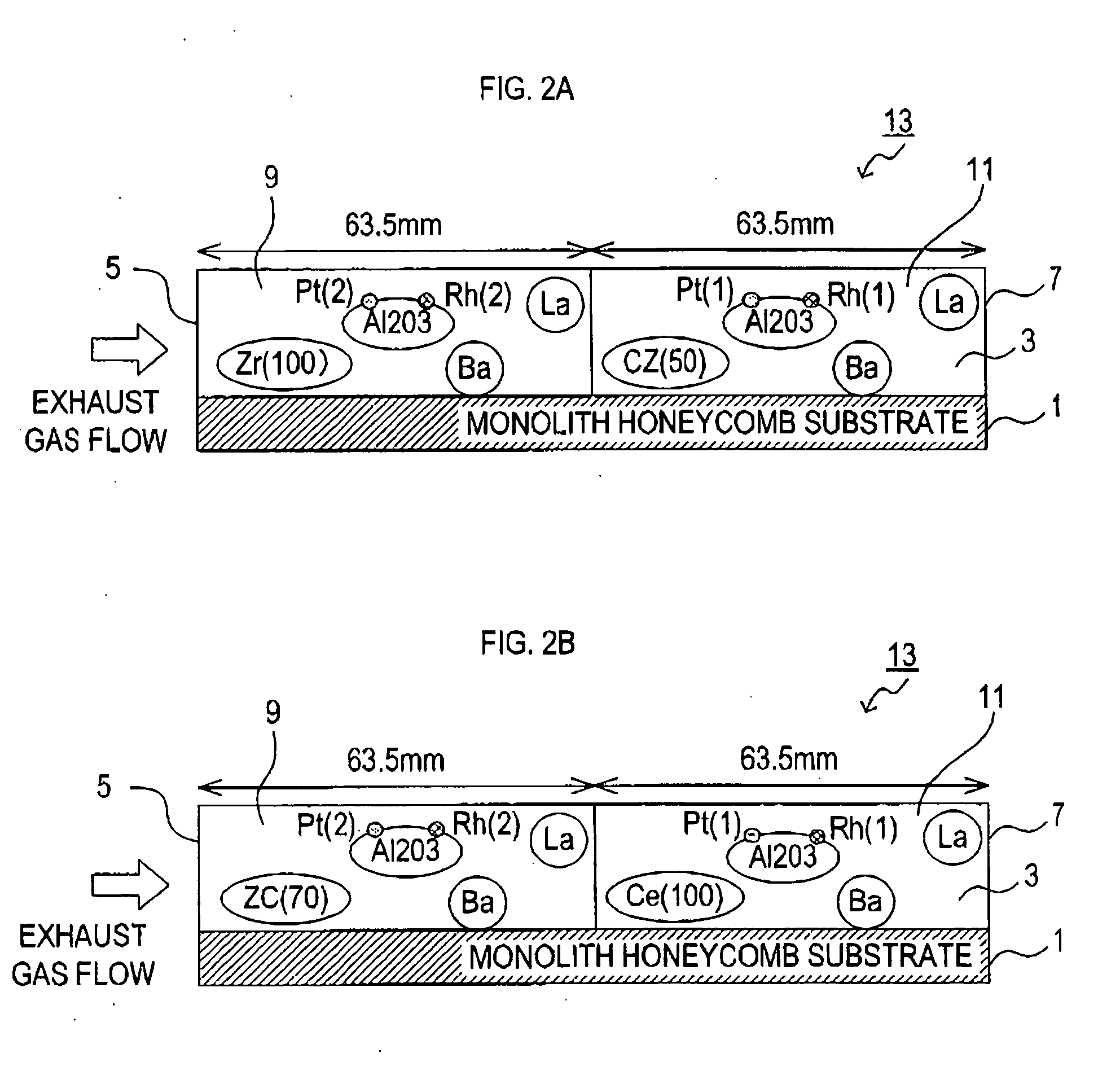
[0085] That is, the ZrCe mixed oxide contained in the slurry S1 in Embodiment 1 is replaced by the Zr oxide in Embodiment 3. As a result, not the ZrCe mixed oxide but the Zr oxide is included in the upstream side catalyst coating layer 9, as shown in FIG. 2A.


PUM

PropertyMeasurementUnit
Fractionaaaaaaaaaa
Fractionaaaaaaaaaa
Fractionaaaaaaaaaa

Abstract

An exhaust gas purifying catalyst comprises a substrate having a through hole serving as a passage for exhaust gas; and a catalyst coating layer formed on an internal surface of the through hole. The catalyst coating layer contains: a component (i): a precious metal; and a component (ii): at least one of a Zr oxide, a Ce oxide and a ZrCe mixed oxide. On an upstream portion of the passage, an oxide equivalent weight of Zr is within a range of 51-100 wt % of an oxide equivalent weight of Zr and Ce contained in the component (ii). On a downstream portion of the passage, the component (ii) includes at least one of a Ce oxide and a ZrCe mixed oxide in which an oxide equivalent weight of Ce is within a range of 58-100 wt % of an oxide equivalent weight of Zr and Ce contained in the ZrCe mixed oxide.

Description

BACKGROUND OF THE INVENTION [0001] (i) Field of the Invention [0002] The present invention relates to an exhaust gas purifying catalyst that removes toxic substances contained in exhaust gas from an internal combustion engine of an automobile, a motorcycle, and others. [0003] (ii) Background Art [0004] A variety of catalysts for purifying exhaust gas emitted from an internal combustion engine of an automobile and the like have been provided. These days, most of the catalysts are three-way catalysts that purify HC, CO, and NOx at the same time. Such catalysts are disclosed, for example, in Publication of Unexamined Japanese Patent Application No. Hei 3-196841, Publication of Unexamined Japanese Patent Application No. Hei 5-23593 and Publication of Unexamined Japanese Patent Application No. 2001-259424. [0005] In one example of the three-way catalyst, one of or a combination of catalytic components, such as Pt, Pd and Rh, is dispersed in and carried by a refractory inorganic compound ...

Claims


Application Information

Patent Timeline
IPC IPC(8): B01J23/10
CPCB01D53/945B01D2255/102B01D2255/407B01J23/63B01J35/0006B01J35/04B01J37/0248Y02T10/22B01D2255/2042B01D2255/2063B01D2255/9032B01D2255/908Y02T10/12
Inventor TAKI, KENICHIHIRAI, AKIMASASUZUKI, HIROMASA
Owner CATALER CORP
Why Eureka
Try Eureka