Small incision intraocular lens with anti-PCO feature

a small incision, intraocular lens technology, applied in the field of intraocular lenses, can solve the problems of unfavorable capsulotomy complications, serious, sight-threatening complications, and difficulty in putting such a method into clinical practice, and achieve the effects of reducing the overall dimension of the optics, maintaining the strength and and increasing the in-situ stability of the iol

Active Publication Date: 2006-06-29
BAUSCH & LOMB INC
View PDF64 Cites 44 Cited by
  • Summary
  • Abstract
  • Description
  • Claims
  • Application Information

AI Technical Summary

Benefits of technology

[0013] The anti-PCO sharp edge is defined by two surfaces forming an acute angle located between a posterior concave region and an outer-most peripheral edge that extends parallel to the optical axis. The sharp edge extends 360° around the posterior optic surface to form a complete barrier to LECs attempting to migrate radially inwardly to the posterior optic surface. On the anterior side, an anterior concave region is formed between the anterior optic surface and an optional peripheral edge surface that extends perpendicular to the optical axis and intersects at a 90° angle with the peripheral edge surface that extends parallel to the optical axis. The posterior and anterior concave regions are preferably located opposite each other and are of substantially the same radius. The one or more haptics which help stabilize the IOL in the eye are preferably spaced from the posterior limit of the outer-most posterior edge surface. The IOL optic is this reduced in size through the anterior and posterior concave regions yet strength and stability of the IOL is maintained. This is due at least in part to the haptic thickness which has not been reduced compared to prior art IOLs of si

Problems solved by technology

One known problem with extracapsular cataract extraction is posterior capsule opacification, or secondary cataract, where proliferation and migration of lens epithelial cells occur along the posterior capsule behind the IOL posterior surface which creates an opacification of the capsule along the optical axis.
Undesirable complications may follow the capsulotomy.
For example, since the posterior capsule provides a natural barrier between the back of the eye vitreous humor and front of the eye aqueous humor, removal of the posterior capsule allows the vitreous humor to migrate into the aqueous humor which can result in serious, sight-threatening complications.
While this approach is logical in theory, putting such a method into clinical practice is difficult due to complications arising, for example, from the toxicity of some of the LEC inh

Method used


Image

  • Small incision intraocular lens with anti-PCO feature
  • Small incision intraocular lens with anti-PCO feature
  • Small incision intraocular lens with anti-PCO feature

Examples


Embodiment Construction

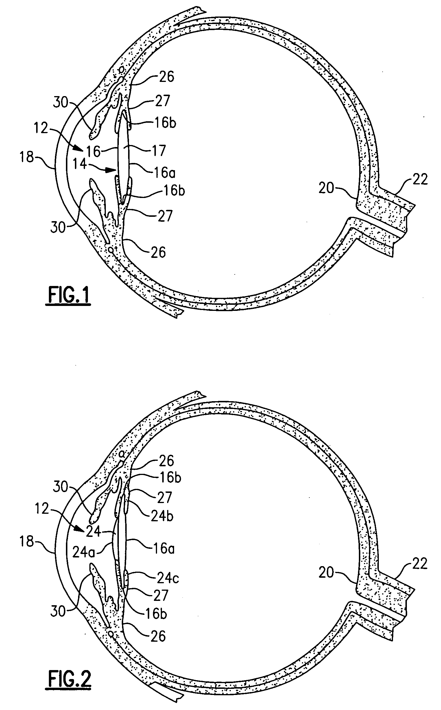
[0025] Referring now to the drawing, there is seen in FIG. 1 a cross-sectional view of a human eye 10 having an anterior chamber 12 and a posterior chamber 14 separated by the iris 30. Within the posterior chamber 14 is a capsule 16 which holds the eye's natural crystalline lens 17. Light enters the eye by passing through the cornea 18 to the crystalline lens 17 which act together to direct and focus the light upon the retina 20 located at the back of the eye. The retina connects to the optic nerve 22 which transmits the image received by the retina to the brain for interpretation of the image.

[0026] In an eye where the natural crystalline lens has been damaged (e.g., clouded by cataracts), the natural lens is no longer able to properly focus and direct incoming light to the retina and images become blurred. A well known surgical technique to remedy this situation involves removal of the damaged crystalline lens which may be replaced with an artificial lens known as an intraocular ...


PUM


Abstract

A thin intraocular lens for inhibiting posterior capsular opacification (PCO) includes an optic having a sharp edge which extends posteriorly and between a posterior concave region and an outer-most peripheral edge surface that extends parallel to the optical axis.

Description

BACKGROUND OF THE INVENTION [0001] The present invention relates to intraocular lenses (IOLs) for implantation in an aphakic eye where the natural lens has been removed due to damage or disease (e.g., a cataractous lens). The present invention more particularly relates to a novel IOL designed in a first aspect to be inserted through a sub-3 mm incision made in the eye, and in a second aspect includes a sharp posterior edge to inhibit unwanted growth of lens epithelial cells (hereinafter “LECs”) between the IOL and posterior capsular bag, also known as posterior capsule opacification (hereinafter “PCO”). [0002] A common and desirable method of treating a cataract eye is to remove the clouded, natural lens and replace it with an artificial IOL in a surgical procedure known as cataract extraction. In the extracapsular extraction method, the natural lens is removed from the capsular bag while leaving the posterior part of the capsular bag (and preferably at least part of the anterior pa...

Claims


Application Information

Patent Timeline
IPC IPC(8): A61F2/16B29D11/00
CPCA61F2/1616A61F2002/009A61F2002/1697A61F2002/1689A61F2002/1699B29D11/00942B29D11/023A61F2/16B29D11/00A61F2/14A61F2/1613
Inventor VAUDANT, JEROMERICHARDSON, GARY A.ALTMAN, GRIFFITHE
Owner BAUSCH & LOMB INC
Why Eureka
Try Eureka