Heat recovery equipment

Active Publication Date: 2006-07-06
MITSUBISHI POWER LTD
View PDF4 Cites 34 Cited by
  • Summary
  • Abstract
  • Description
  • Claims
  • Application Information

AI Technical Summary

Benefits of technology

[0012] It is an object of the present invention to at l

Problems solved by technology

However, the conventional equipment does not make fully effective use of heat.
However, a heat extractor unit capable of

Method used


Image

  • Heat recovery equipment
  • Heat recovery equipment
  • Heat recovery equipment

Examples


first embodiment

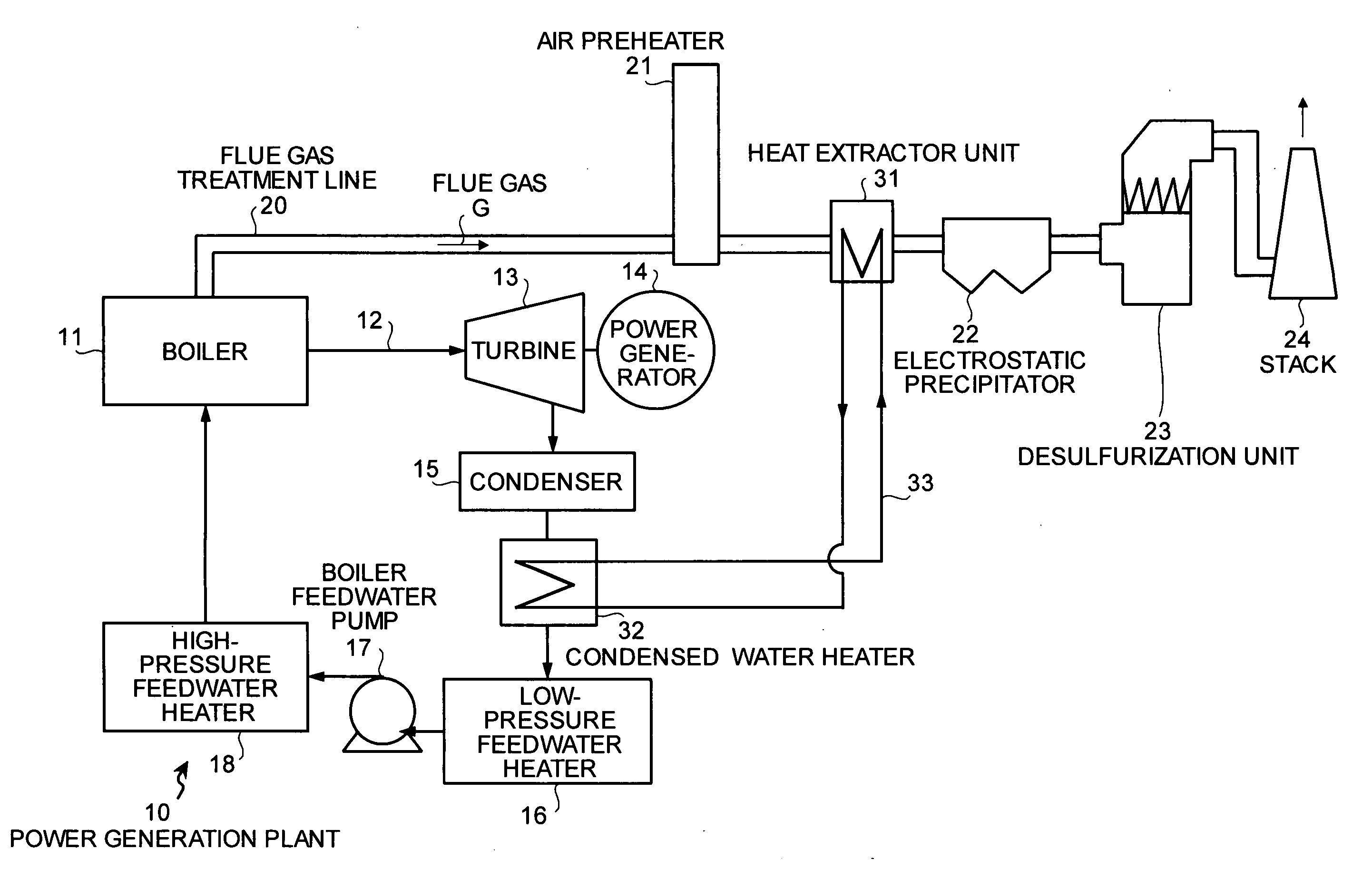
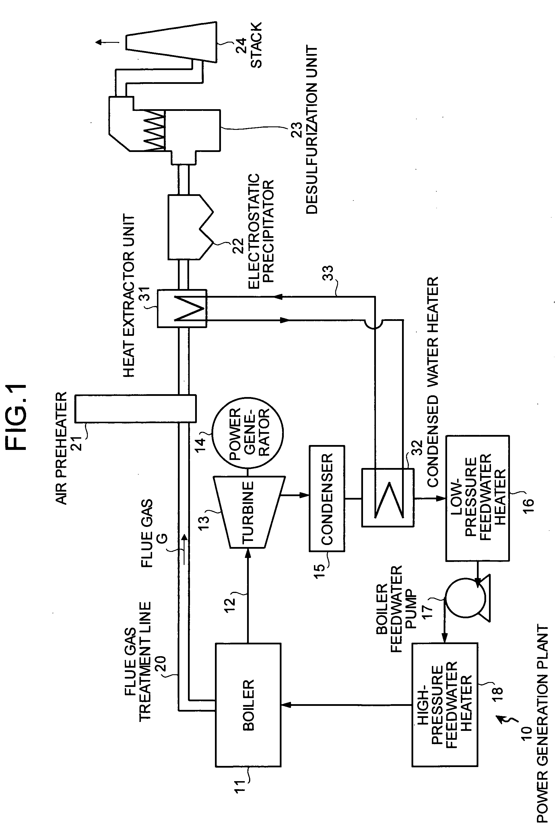
[0040]FIG. 1 is a schematic of heat recovery equipment according to the present invention.

[0041] The heat recovery equipment, which recovers heat from flue gas G, includes a power generation plant 10 that drives a steam turbine 13 by superheated steam 12 from a boiler 11, and a flue gas treatment line 20 that treats the flue gas G from the boiler 11. The heat recovery equipment also includes a heat extractor unit 31 and a condensed water heater 32. The heat extractor unit 31 is provided between an air preheater 21 and a dry ESP 22 that are provided on the flue gas treatment line 20. The condensed water heater 32 is interposed between a condenser 15, which is provided on a condensed water line of the power generation plant 10, and a low-pressure feedwater heater 16, and heats condensed water by heat recovered by the heat extractor unit 31. The heat recovery equipment includes a desulfurization unit 23 that removes sulfur oxides in the flue gas, and a stack 24.

[0042] An example of a ...

third embodiment

[0072] In the third embodiment, a coolant can be directly pumped up from a sea, a lake, or a river and passed through the heat remover 70 so as to reduce the flue gas temperature.

[0073] Moreover, a recovered heat medium can be discharged to the sea, the lake, or the river.

[0074]FIG. 7 is a conceptual diagram of heat recovery equipment according to a fourth embodiment. In FIG. 7, like constituent elements of the equipment as those of the heat recovery equipment according to the first embodiment shown in FIG. 1 are denoted by like reference numerals, and redundant explanations thereof are omitted.

[0075] The equipment according to the first embodiment includes the condensed water heater 32 so as to recover the heat. According to the fourth embodiment, the equipment is configured so that a preheater 38 for the air that heats air 37 introduced through a forced draft fan 61 is provided in a front side of the air preheater 21 that preheats the air to be supplied to the boiler 11.

[0076] ...

fifth embodiment

[0077]FIG. 8 is a conceptual diagram of heat recovery equipment according to a In FIG. 8, like constituent elements of the equipment as those of the heat recovery equipment shown in FIGS. 1 to 7 are denoted by like reference numerals, and redundant explanations thereof are omitted.

[0078] The heat recovery equipment is a combination of the heat recovery equipment according to the first embodiment shown in FIG. 1 and the heat recovery equipment according to the fourth embodiment shown in FIG. 7. In addition, the heat recovery equipment according to the fifth embodiment is configured so that a first regulating valve 39-1 and a second regulating valve 39-2 that regulate an amount of the heat medium flowing into either the condensed water heater 32 or the preheater 38 for the air are provided on heat medium lines 33-1 and 33-2, respectively.

[0079] By providing the first regulating valve 39-1 and the second regulating valve 39-2, excessive heat supply for heating either the condensed wa...


PUM


Abstract

Heat recovery equipment recovers heat from flue gas. The heat recovery equipment includes a power generation plant that drives a steam turbine by superheated steam produced in a boiler, and an exhaust-gas treatment line that treats flue gas output from the boiler. The exhaust-gas treatment line includes a first air preheater, a heat extractor unit, and a dry electrostatic precipitator. The power generation plant includes a condensed water line. The condensed water line includes a condenser, a condensed water heater, and a low-pressure feedwater heater. The condensed water heater heats water condensed by the condenser with the heat recovered by the heat extractor unit.

Description

BACKGROUND OF THE INVENTION [0001] 1. Field of the Invention [0002] The present invention relates to a technology for recovering heat of flue gas from a boiler. [0003] 2. Description of the Related Art [0004] It is known to recover heat of flue gas from a coal burning boiler. Specifically, the heat of the flue gas is recovered before discharging the flue gas. [0005]FIG. 19 is a schematic of a conventional heat recovery equipment disclosed in Japanese Patent Application Laid-open No. H11-179147. In the conventional heat recovery equipment, untreated flue gas A1 discharged from a coal burning boiler 1 is introduced first into heat recovery equipment of an air heater (AH) 2, where heat is recovered from the flue gas A1, and air B to be supplied to the boiler 1 is heated with the recovered heat. As a result of recovery of the heat from the flue gas A1, the temperature of the flue gas A1 drops down to 120° C. to 160° C. [0006] The flue gas A1 is then introduced into a heat extractor unit...

Claims


Application Information

Patent Timeline
IPC IPC(8): B60K6/04F22D1/02F22D11/00F23J3/00F23L15/02F28F21/08
CPCF22D1/36
Inventor TAKEUCHI, YASUHIRONAKAYAMA, YOSHIOOISHI, TSUYOSHINAKAMURA, SATOSHINAKAMURA, SHINJIDOHI, TSUYOSHINAGATA, CHIKAYUKI
Owner MITSUBISHI POWER LTD
Why Eureka
Try Eureka