Sensor device for tire

a technology of a sensor device and a tire, which is applied in the direction of vehicle tyre testing, instruments, roads, etc., can solve the problems of lowering the workability of assembly of the rim, affecting the transmission efficiency, and affecting the assembly efficiency of the rim, so as to achieve excellent transmission capability, facilitate the displacement of the fore-end portion of the antenna by centrifugal force, and improve the effect of transmission efficiency

Inactive Publication Date: 2006-07-06
YOKOHAMA RUBBER CO LTD
View PDF2 Cites 6 Cited by
  • Summary
  • Abstract
  • Description
  • Claims
  • Application Information

AI Technical Summary

Benefits of technology

[0012] It is preferable that a length of the antenna be ½, ¼, ⅛ or 1/16 of a wavelength of electromagnetic waves used for communication. Thus, more excellent transmission capability can be achieved. Moreover, it is preferable that an insulating weight be attached to the fore-end portion of the antenna. Thus, displacement of the fore-end p...

Problems solved by technology

Thus, if the printed board is disposed parallel to the well part, there is a problem that transmission efficiency is extremely deteriorated.
Ho...

Method used


Image

  • Sensor device for tire
  • Sensor device for tire
  • Sensor device for tire

Examples


first embodiment

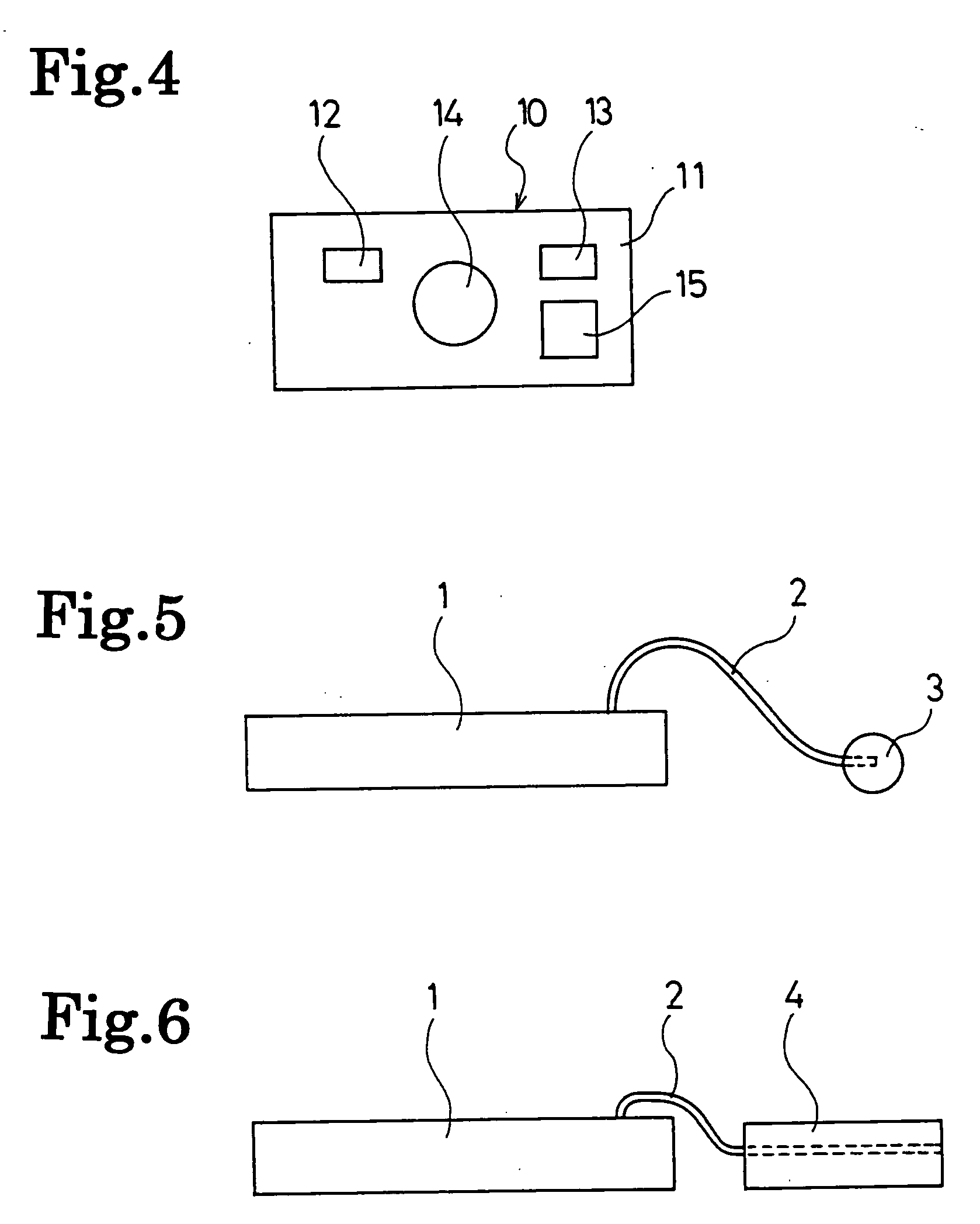
[0031]FIG. 5 shows a state where an insulating weight 3 is attached to the fore-end portion 2a of the antenna 2 in the sensor device for a tire according to the As shown in FIG. 5, by attaching the weight 3 to the fore-end portion 2a of the antenna 2, displacement of the fore-end portion 2a of the antenna 2 can be facilitated by centrifugal force acting on the weight 3 in the rotation of the tire. Moreover, since the weight 3 has insulating properties, the antenna 2 and the rim are never electrically connected to each other.

[0032]FIG. 6 shows a state where the antenna 2 is covered with an insulating spacer 4 in the sensor device for a tire according to the first embodiment. As shown in FIG. 6, by covering the antenna 2 with the insulating spacer 4, radio interference caused by the rim during stopping is avoided, and more excellent transmission capability can be achieved. As such a spacer, a sponge and the like can be used.

[0033] Note that, although the weight 3 and the spacer 4 ca...

second embodiment

[0036]FIG. 9 shows a state where an insulating weight 23 is attached to the fore-end portion 22a of the antenna 22 in the sensor device for a tire according to the As shown in FIG. 9, by attaching the weight 23 to the fore-end portion 22a of the antenna 22, displacement of the fore-end portion 22a of the antenna 22 can be facilitated by centrifugal force acting on the weight 23 in the rotation of the tire. Moreover, since the weight 23 has insulating properties, the antenna 22 and the rim are never electrically connected to each other.

[0037]FIG. 10 shows a state where the antenna 22 is covered with an insulating spacer 24 in the sensor device for a tire according to the second embodiment. As shown in FIG. 10, by covering the antenna 22 with the insulating spacer 24, radio interference caused by the rim during stopping is avoided, and more excellent transmission capability can be achieved.

[0038]FIGS. 11 and 12 show a sensor device for a tire according to a third embodiment of the p...


PUM


Abstract

A sensor device for a tire, having enhanced transmission capability without disturbing the assembly of a rim to the tire. With itself installed in the tire, the sensor device detects information inside the tire and transmits the result to the outside. The sensor device has a case for receiving an electronic component and an antenna electrically connected to the electronic component and extended to the outside of the case. The fore-end portion of the antenna is made to be displaceable outwardly in the tire radial direction by centrifugal force generated in the rotation of the tire.

Description

TECHNICAL FIELD [0001] The present invention relates to a sensor device for a tire, which detects information inside the tire such as an internal pressure, and more particularly relates to a sensor device for a tire having enhanced transmission capability without disturbing assembly of a rim to the tire. BACKGROUND ART [0002] In order to monitor information inside a tire, such as an internal pressure and temperature, there has been heretofore performed attachment of a sensor device to a well part of a rim, detection of the information inside the tire by use of the sensor device, and transmission of the detection results to a receiver outside of the tire by utilizing radio waves. [0003] In such a sensor device for a tire, generally, a sensor and a transmitter are mounted on a printed board, a transmission antenna is printed on the printed board, and these sensor and transmitter are housed in a thin case together with the printed board. [0004] Upon attachment of the sensor device desc...

Claims


Application Information

Patent Timeline
IPC IPC(8): G01M17/02B60C23/04G01L17/00B60C23/20G08C17/02H01Q1/22
CPCB60C23/0408H01Q1/2241B60C23/0498
Inventor SHIMURA, KAZUHIRO
Owner YOKOHAMA RUBBER CO LTD
Why Eureka
Try Eureka