
Wellbore consolidating tool for rotary drilling applications

a technology of rotary drilling and consolidating tools, which is applied in the direction of drilling pipes, drilling holes/well accessories, sealing/packing, etc., can solve the problems of high degree of wear and tear, inability to use tools in most applications, and damage to formation permeability and lubricating fractures, etc., to increase the resistance to wear and tear downhole

Inactive Publication Date: 2006-07-06
SCHLUMBERGER TECH CORP
View PDF14 Cites 46 Cited by
  • Summary
  • Abstract
  • Description
  • Claims
  • Application Information

AI Technical Summary

Benefits of technology

[0016] Also the subpart is adapted to exert only minimal forces in non-radial directions. Specifically it is adapted to reduce or minimize lateral forces in direction of the axis of the borehole. The device thus generates low resistance against the progress of the drill bit and avoids scraping or cutting actions in this direction.
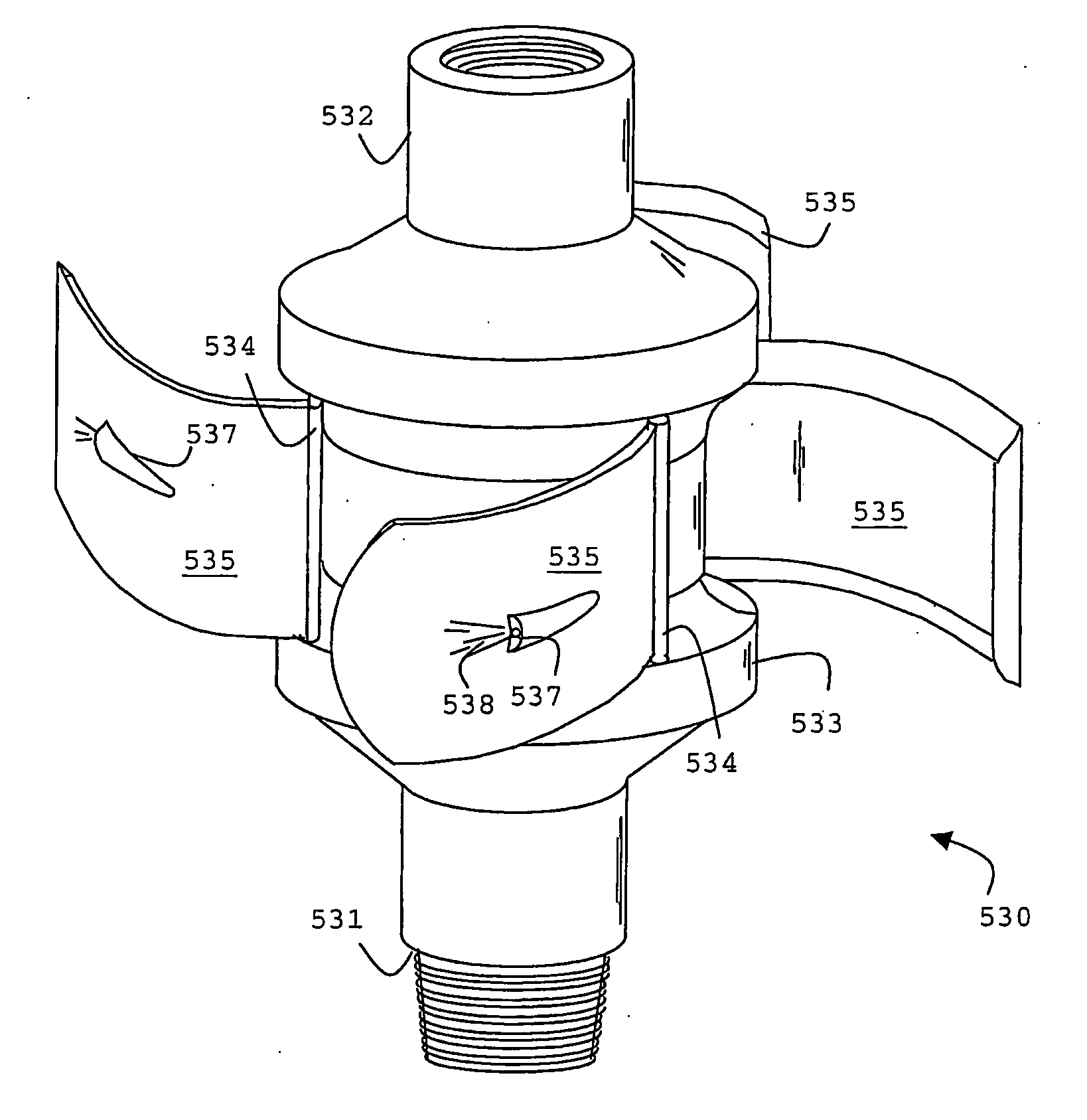
[0018] To resist the abrasive nature of the interaction with the filter cake and the cuttings, at least the parts of the surface that contact the wall of the borehole are made of a hard metal, such as steel, or include specific abrasive-resistant pads, for example pads of silicone carbide or other engineering ceramics. Preferably the flexible elements of the subparts are also made from metal, exploiting the inherent flexibility of thin metal.
[0022] In a further preferred embodiment of the invention the subpart includes a compliant structure extending under operating conditions from a central tubular body towards the wall of the wellbore. The compliant structure may include elastic elements or flexures that exhibit a restoring force when deformed or compressed, or exert a pressure onto the wall of the borehole. The elements of flexures are preferably made from metal to increase the resistance against wear and tear downhole.

Problems solved by technology

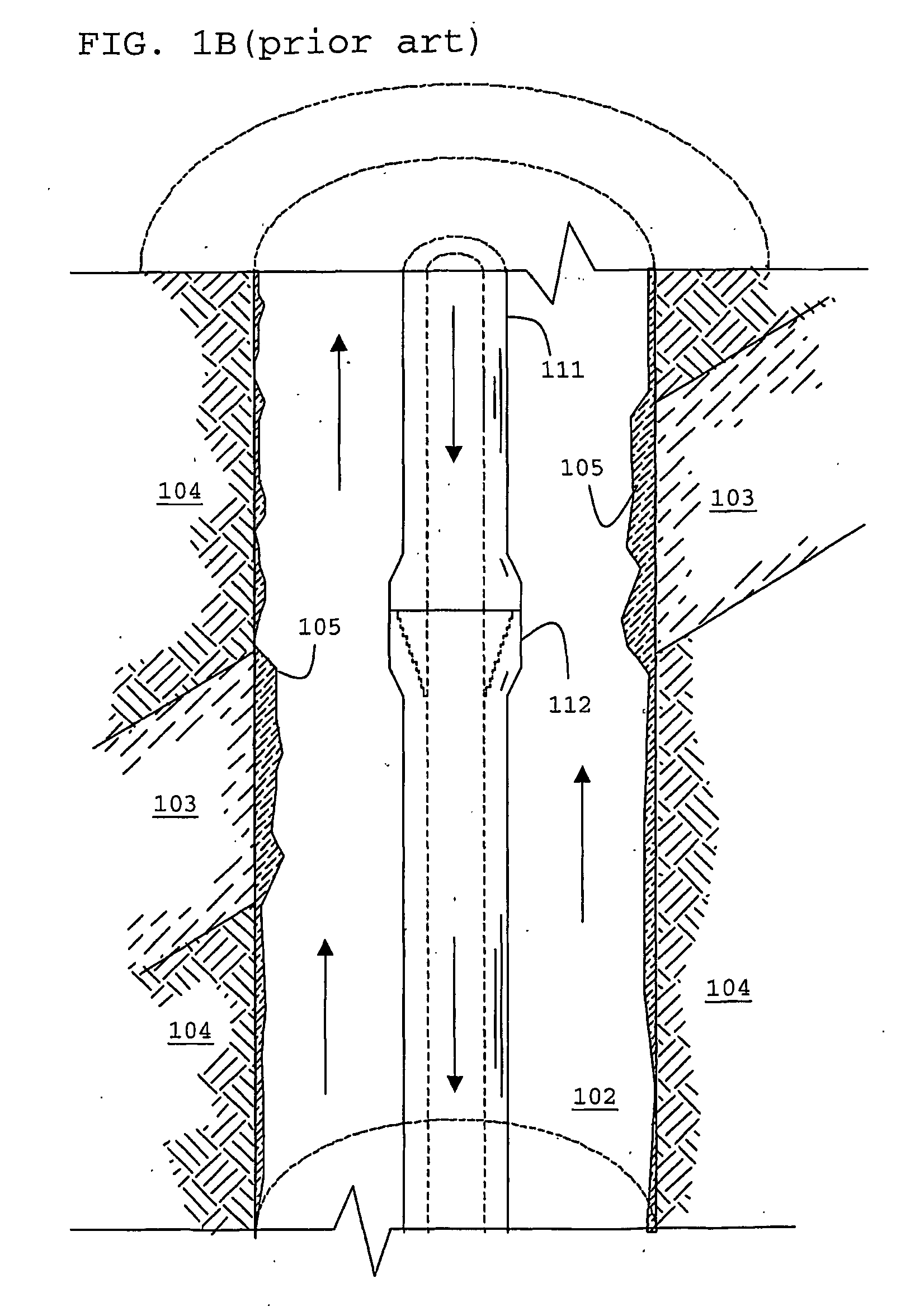
The mud cake layer prevents further fluid loss, which can be harmful, damaging formation permeability and lubricating fractures.
However rubber when exposed to the hostile environment close to the drill bit exhibits a high degree of wear and tear, making the tool impractical for most applications.

Method used


Image

  • Wellbore consolidating tool for rotary drilling applications
  • Wellbore consolidating tool for rotary drilling applications
  • Wellbore consolidating tool for rotary drilling applications

Examples


Embodiment Construction

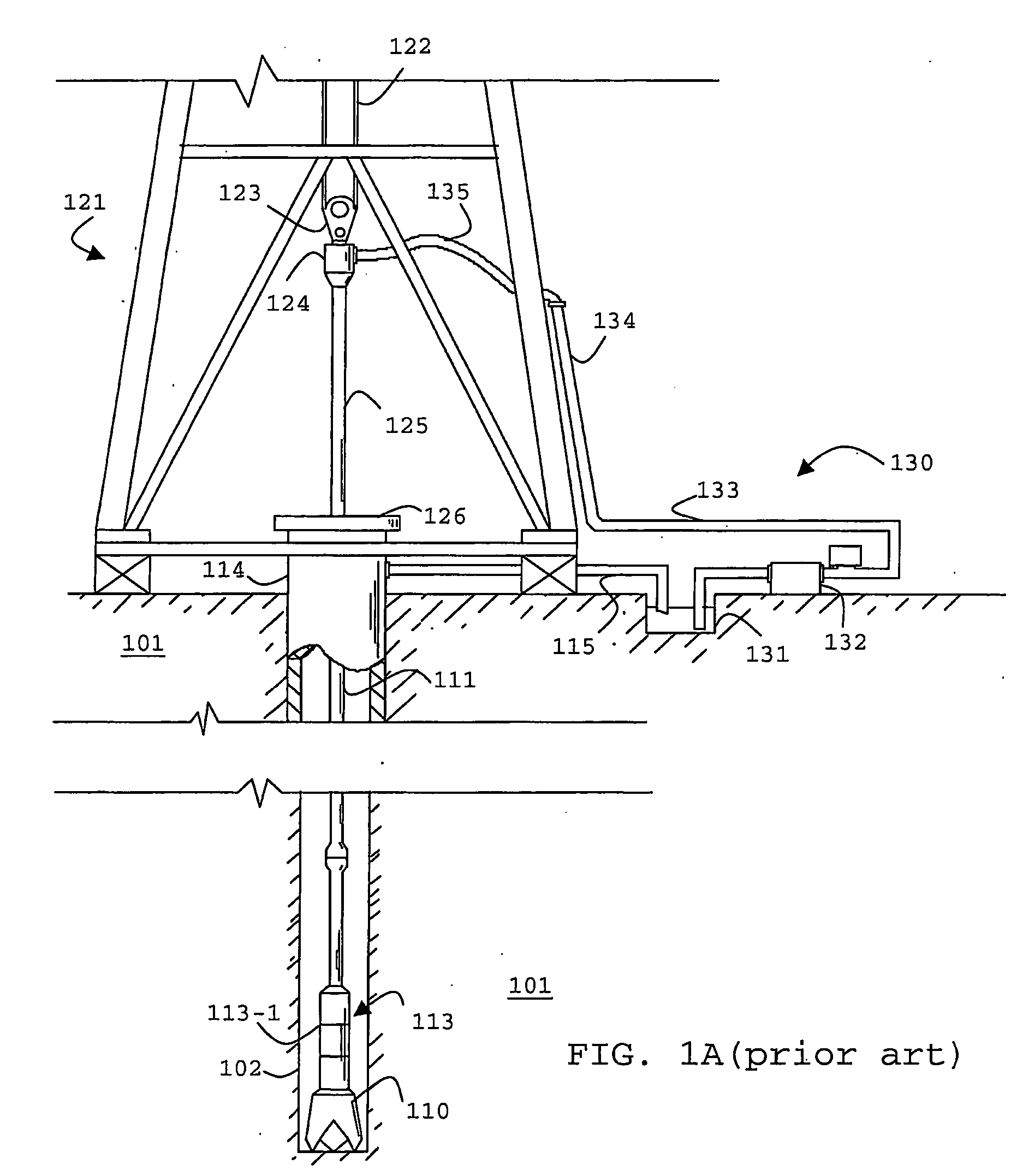
[0038] In FIG. 1, there is shown a known well drilling system for rotary drilling operations. A drill string 111 is shown within a borehole 102. The borehole 102 is located in the earth 101. The borehole 102 is being cut by the action of the drill bit 110. The drill bit 110 is disposed at the far end of a bottom hole assembly (BHA) 113 that is attached to and forms the lower portion of the drill string 111. The bottom hole assembly 113 contains a number of devices including several drill collars 113-1 to increase the weight on the bit 110.

[0039] The drilling surface system includes a derrick 121 and a hoisting system, a rotating system, and a mud circulation system 130. The hoisting system which suspends the drill string 111, includes the draw works 122, a hook 123 and a swivel 124. The rotating system includes a kelly 125, a rotary table 126, and engines (not shown). The rotating system imparts a rotational force on the drill string 111 during a rotational drilling operation in a ...


PUM


Abstract

A subpart (430) of a drill string (211) is described having an outer circumferential surface which is contoured and adapted to engage the wall of the borehole with a small angle of attack while exerting during rotary drilling operations an compacting pressure on mud cake and / or cuttings present in the annulus between the drill string and the borehole.

Description

[0001] The present invention generally relates to apparatus and methods for improving the stability of a wellbore during drilling operations using a rotary drill string. More specifically, it relates to such apparatus and methods to enhance the performance of the filter or mud cake layer on the wall of the wellbore as protective and isolating layer. BACKGROUND OF THE INVENTION [0002] To obtain fluids, such as oil and gas, from a subterranean reservoir boreholes or wells are drilled from the surface into the reservoir. The most commonly applied method to drill a well uses a derrick or mast structure, in which a drill string is assembled and continuously extended into the borehole as the drilling progresses. Drilling is performed by rotating a drill bit attached to the end of the drill string. During the drilling process pressurized drilling fluid (commonly known as “mud” or “drilling mud”) is pumped from the surface into the hollow drill string to provide lubrication to various membe...

Claims


Application Information

Patent Timeline
IPC IPC(8): E21B7/00E21B37/00E21B17/10E21B33/138
CPCE21B17/1014E21B33/138
Inventor COOPER, IAINVERCAEMER, CLAUDELESSO, WILLIAMJEFFRYES, BENJAMIN PETERSHEPPARD, MICHAEL CHARLES
Owner SCHLUMBERGER TECH CORP
Learn More