Modular ozone generator with an air diffuser

Active Publication Date: 2006-07-06
HAYWARD IND INC
View PDF78 Cites 12 Cited by
  • Summary
  • Abstract
  • Description
  • Claims
  • Application Information

AI Technical Summary

Benefits of technology

[0008] A modular ozone generator includes a tubular UV lamp disposed within a chamber for emitting radiation in the ultraviolet frequency range to cause conversion of some of the oxygen molecules within the chamber into ozone molecules to produce ozonated air. Air inflows into the chamber through a diffuser having a number of inlets surrounding or adjacent the UV lamp. During irradiation of the oxygen molecules by the UV lamp, the resulting ozone molecules will migrate downwardly within the chamber as the ozone molecules are heavier than the oxygen molecules. This results in a higher concentration of ozone molecules at the bottom of the chamber. To take advantage of the increased concentration of ozone molecules in the air at the lower part of the chamber, an outlet is formed therein. When two or more modules are used, the second module is placed beneath the first module and its inlet is connected with the outlet of the first module. Thereby, the air with the higher conc

Problems solved by technology

Some of these chemicals may be hazardous to the health of a user of the swimming pool or spa for a period of time until the chemicals have dissipated or otherwise been rendered impotent.
There have been some instances of injecting ozone into the return line of swimming pools and spas but for the most part, such installations have not been functionally or practically successful.
The main reason f

Method used


Image

  • Modular ozone generator with an air diffuser
  • Modular ozone generator with an air diffuser
  • Modular ozone generator with an air diffuser

Examples


Embodiment Construction

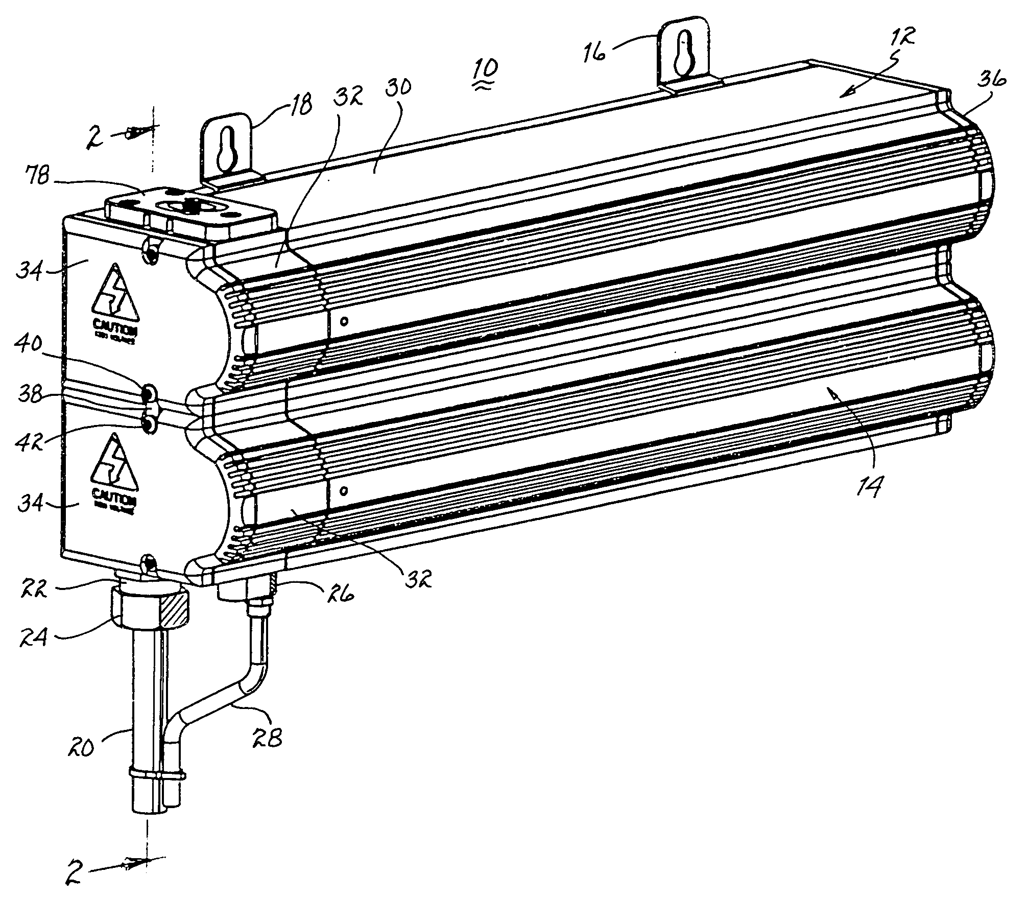
[0033] Referring to FIG. 1, there is illustrated an ozone generator 10 formed of a first module 12 and a second module 14. Each of these modules constitutes an ozone generator. Upon actuation, each module will generate ozone enriched air (ozonated air) for discharge at its outlet. By cascading the modules, as illustrated in FIG. 1, the degree of concentration of ozone in the air ultimately discharged from ozone generator 10 will be enhanced. It is to be understood that one or more further modules may be serially connected and extending downwardly.

[0034] Each ozone generator 10 is primarily intended for use with a swimming pool or spa. Depending upon the amount of water in the pool or spa, one or more modules (12, 14) may be used to ensure an effective degree of entrainment of the ozone in the water to ensure oxidization of organic material that may be present. In particular, it is intended that the ozone, upon coming in contact with micro-organisms, destroys such micro-organisms.

[...


PUM


Abstract

A modular ozone generator includes an ultraviolet (UV) lamp within a chamber for converting some of the oxygen molecules in air to ozone molecules. The air is introduced through an inlet at a high point of the chamber and discharged through an outlet at a low point of the chamber to increase the proportion of ozone molecules relative to the oxygen molecules discharged due to the higher density ozone molecules migrating downwardly. The introduced air is conveyed through a diffuser to provide multiple streams of air flowing about the lamp to enhance irradiation of the oxygen molecules and form ozone molecules. A second or more ozone generator modules are beneath the first ozone generator module with an interlocking mechanism to align the outlet of an upper ozone generator with the inlet of a lower ozone generator module. The number of cascaded ozone generator modules forming a vertical stack is a function of the concentration (and amount) of ozone molecules sought to be generated. Readily removable end caps for each ozone generator module accommodate repair and replacement of any and all internal components with or without dismounting the ozone generator module from its supporting structure. Slidably mounted tabs accommodate attachment of the ozone generator modules to hard points of the supporting structure.

Description

CROSS REFERENCE TO RELATED APPLICATIONS [0001] The present application is a continuation-in-part application of an application entitled “Modular Ozone Generator” assigned Ser. No. 11 / 029,288, filed Jan. 5, 2005 and assigned to the present assignee.BACKGROUND OF THE INVENTION [0002] 1. Field of the Invention [0003] The present invention relates to ozone generators and, more particularly, to stackable modular ozone generators particularly adapted for use in ozonating the air in the return line of a swimming pool or spa. [0004] 2. Description of Related Prior Art [0005] All modern swimming pools and spas include a pump for recirculating the water through a filtration apparatus. The filtration apparatus filters and collects organic and inorganic matter suspended in the water passing through the filter. The micro-organisms that may be part of the organic matter are usually responsible for algae and other organic contaminations of the water in the swimming pool or spa. Conventional treatm...

Claims


Application Information

Patent Timeline
IPC IPC(8): C01B13/00B01J19/08B01J19/12
CPCC01B13/10
Inventor BARNES, STEVEN R.CONN, RICHARD D.GRAY, ROBERT J. III
Owner HAYWARD IND INC
Why Eureka
Try Eureka