

Apparatus and process for the production of metals in stacked electrolytic cells
a technology of electrolytic cells and apparatus, applied in the field of electrochemical reduction of alkali metal salts, can solve the problems of energy consumption contributing to the cost of production
- Summary
- Abstract
- Description
- Claims
- Application Information
AI Technical Summary
Benefits of technology
Problems solved by technology
Method used
Image

Examples
example 1
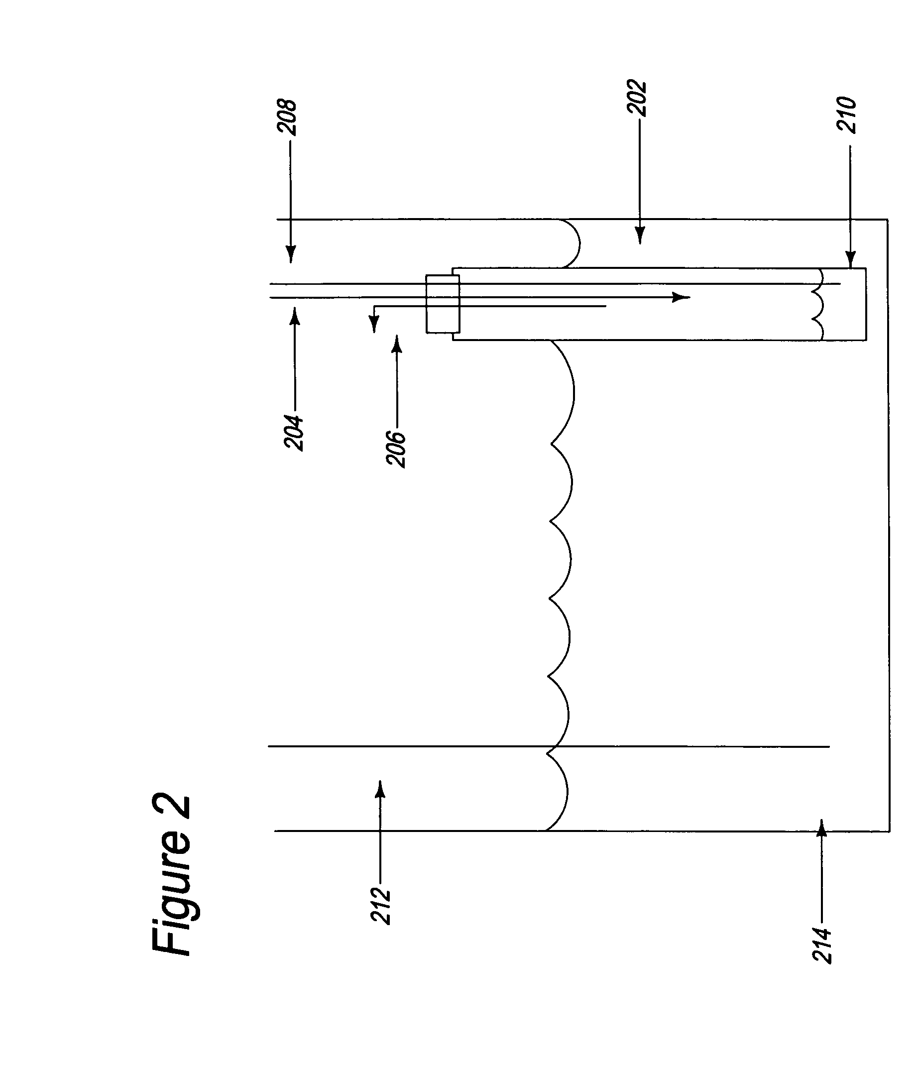
[0040] As a demonstration of the process in a single electrolytic cell, 200 mL of 50 wt-% NaOH aqueous solution was placed in an electrolytic cell, as illustrated in FIG. 2. One end (e.g., the bottom) of a ceramic tube 202 constructed from Na β″-alumina was immersed in the solution of NaOH to act as the ionic membrane separator. The bottom end of the tube was closed. The top end of the tube was situated so that it extended above the surface of the NaOH solution. The top end was open, but sealed with a rubber septum. The interior of the tube comprised the cathode compartment. A needle 204 pierced the septum to act as an inlet for nitrogen gas, while a second needle 206 pierced the septum to act as an outlet for nitrogen gas. The cathode compartment was blanketed by nitrogen gas, to provide an inert atmosphere and to protect the cathode compartment from exposure to the air and moisture.
[0041] Before operation of the electrolytic cell, the tube was seeded with about 1 gram of sodium m...
example 2
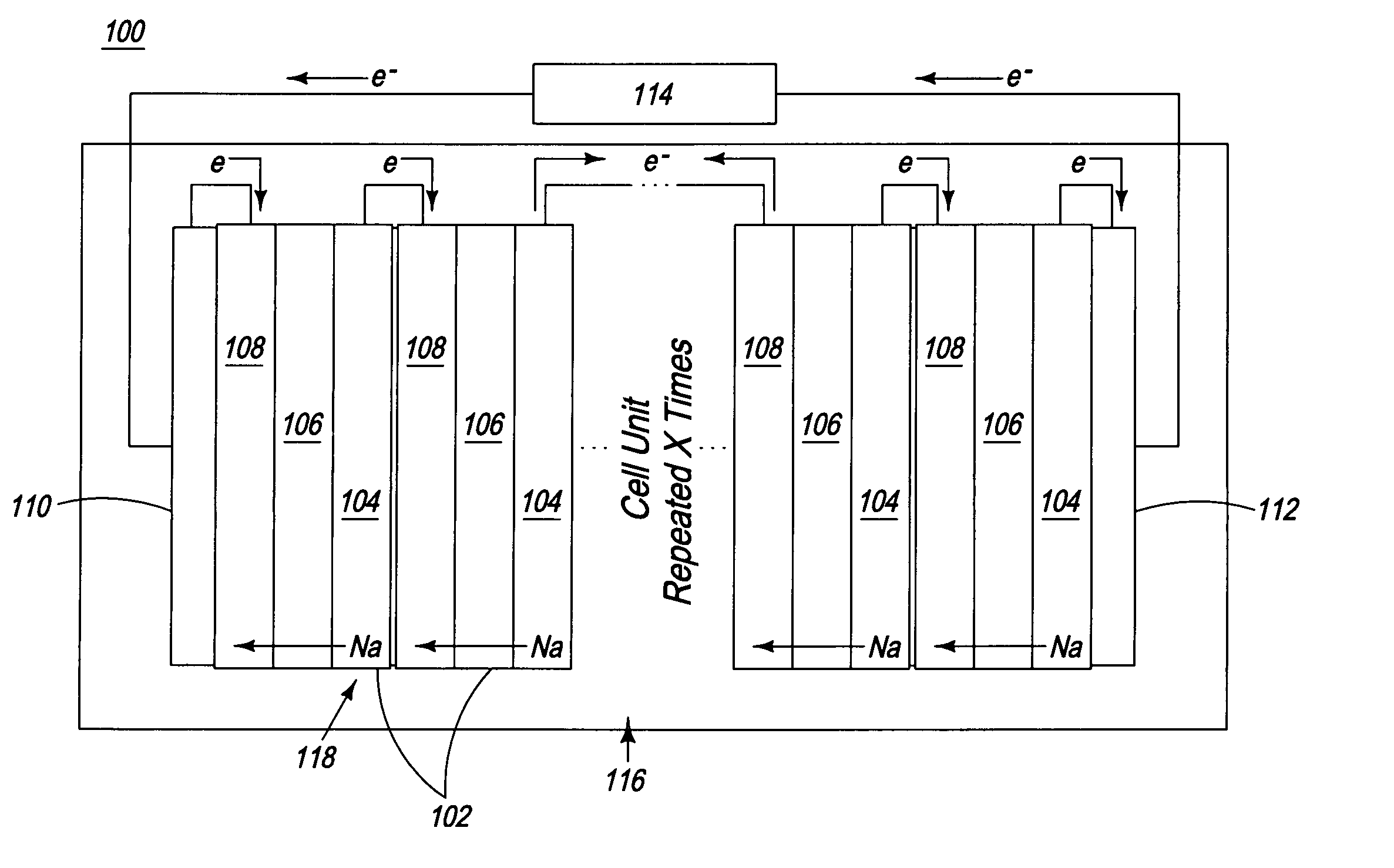
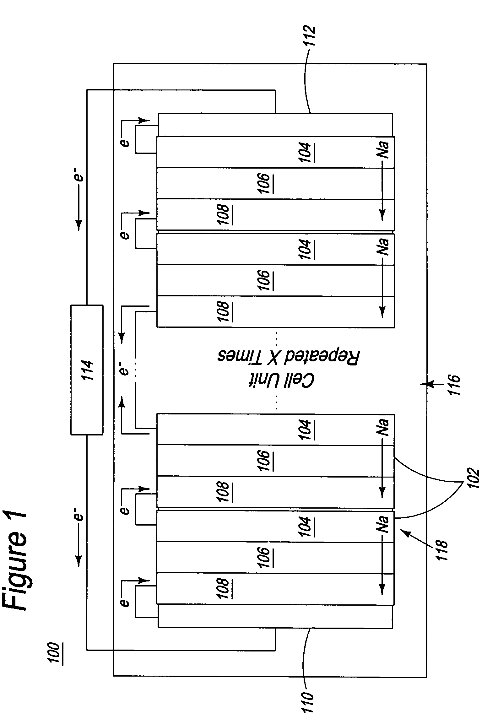
[0045] The sodium generating process as described in Example 1 was repeated by connecting two cells as shown in FIG. 2 (connected in series to form a two-cell stack). In this case, the anode of cell 1 was connected to the cathode of cell 2. The cathode compartment of each cell was seeded with about 1 gram of sodium metal. A potentiostat supplied 8 V of potential across the stack, so each cell experienced an average voltage of 4 V, and 1600 mAh of charged passed through the stack to generate sodium metal in the cathode compartments of both cells. The amount of sodium generated during this electrolysis was not quantified, but the presence of sodium was verified visually and by hydrolysis. In theory, the 1600 mAh of electricity would generate 1.37 g of sodium metal per cell, for a total of 2.74 g of sodium from the stack, assuming quantitative yield. On hydrolysis, each cell would produce 730 mL of H2 gas from the sodium generated, and the 1 gram seed generates an additional 523 mL of ...
example 3
[0046] A two-cell stack was constructed as described in Example 2 and sodium metal was produced under the hydrogen-assisted sodium generation in molten NaOH conditions shown in Equation (2). Two heating mantles were placed next to each other, and an α-alumina crucible containing 400 g of NaOH was placed inside each mantle. The mantles were both held above about 350° C., with reactor 1 operated at about 351° C., and reactor 2 operated at about 368° C. This melt comprised the anolyte and the anode compartment. The anode in each reactor was a nickel tube terminating in a nickel sparger. Hydrogen gas from a common source passed through each sparger into the anode compartment. The gas outlets of the two reactors were joined together to feed a common bubbler, to equalize the hydrogen pressure in the two reactors.
[0047] A sodium β″-alumina tube charged with 0.5 g NaOH was inserted into each melt. A nickel wire was in contact with the molten NaOH inside each sodium β″-alumina tube. These w...
PUM
| Property | Measurement | Unit |
|---|---|---|
| Temperature | aaaaa | aaaaa |
| Temperature | aaaaa | aaaaa |
| Temperature | aaaaa | aaaaa |
Abstract
Description
Claims
Application Information