Cooling apparatus and projection type display device

Inactive Publication Date: 2006-07-06
SONY CORP
View PDF11 Cites 6 Cited by
  • Summary
  • Abstract
  • Description
  • Claims
  • Application Information

AI Technical Summary

Benefits of technology

[0016] According to the embodiments of the present invention, there is an advantage in that each cooling fan can be operated with the required lowest limit of speed without inducing an increase in the system size, and the power consumption and the generated noise can be suppressed.

Problems solved by technology

In the above system, however, a voltage A′ actually supplied to the fan for the calculated result A ends up being affected by the digital-analog conversion circuit and the amplification circuit, so has error.
For this reason, the past cooling apparatus has the disadvantages of a large wasteful consumption of power and generation of noise.
In order to eliminate this error, in the art, processing has been performed to sense the speed of the fan and feed it back so as to obtain the desired speed, but this was disadvantageous in that the system ended up becoming relatively large.

Method used


Image

  • Cooling apparatus and projection type display device
  • Cooling apparatus and projection type display device
  • Cooling apparatus and projection type display device

Examples


Embodiment Construction

[0025] Below, embodiments of the present invention will be explained with reference to the attached drawings.

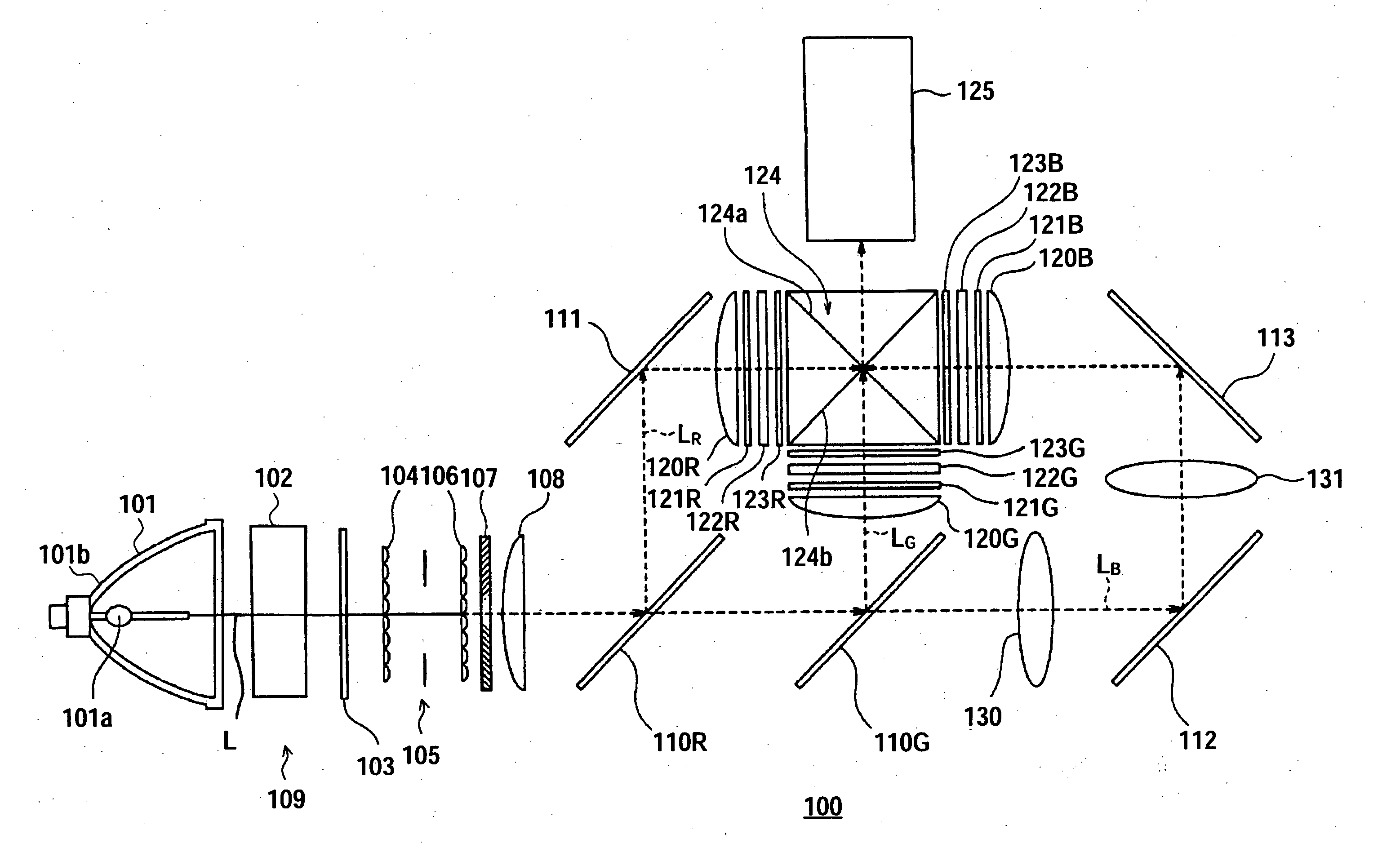
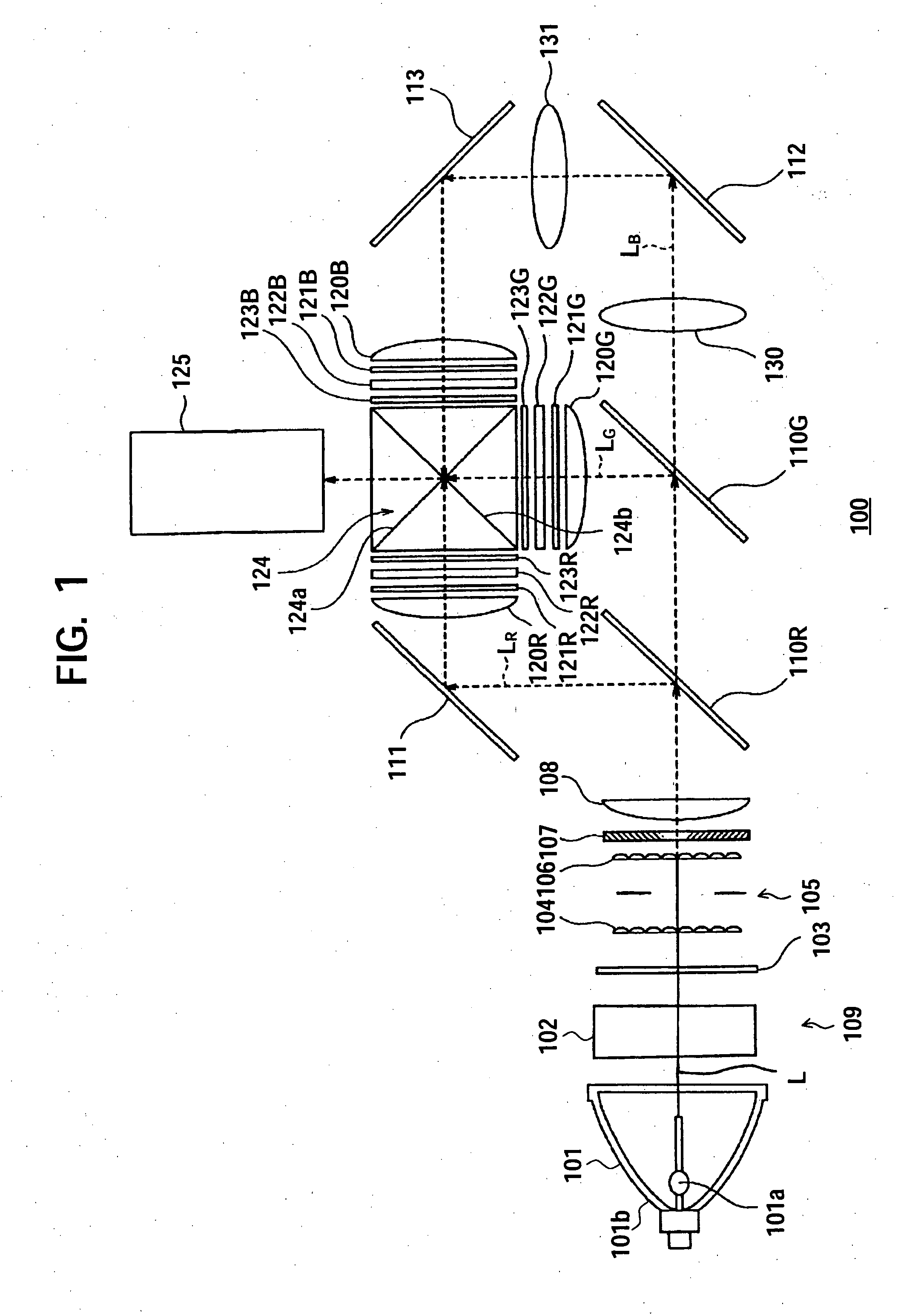
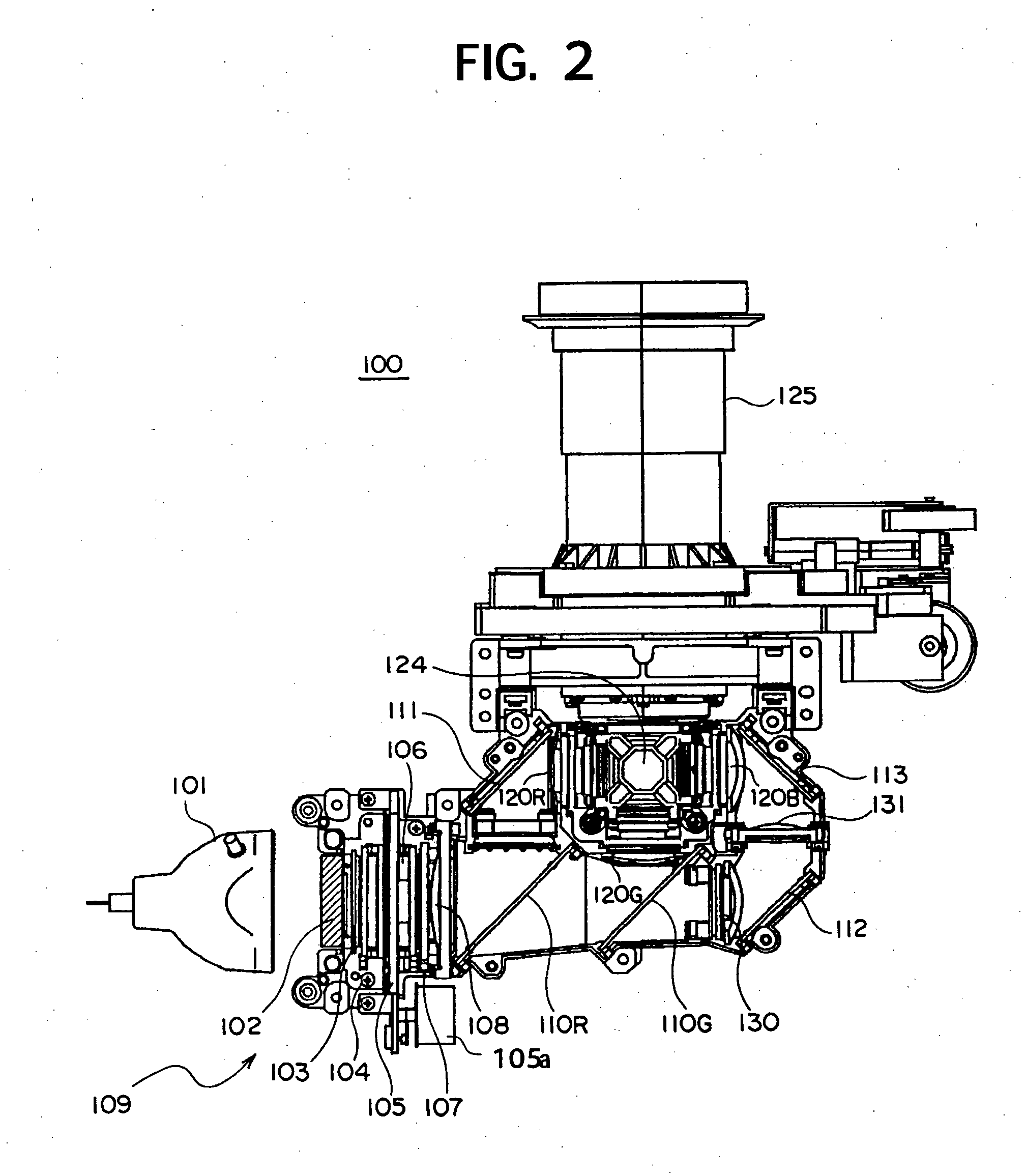
[0026]FIG. 1 is a diagram showing the principle of a liquid crystal projector (projection type display device) according to an embodiment of the present invention. FIG. 2 is a diagram showing more specifically a liquid crystal projector (projection type display device) according to an embodiment of the present invention. FIG. 3 is a system block diagram of a control system of a cooling apparatus according to the present embodiment applied to the liquid crystal projector of FIG. 1 and FIG. 2.

[0027] The liquid crystal projector 100 is, as shown in FIG. 1 and FIG. 2, constituted by a light source 101, a collimator lens 102, an optical filter 103, a first multi-lens array (MLA) 104, an iris device 105, a second MLA 106, a polarization conversion device 107, a condenser lens 108, dichroic mirrors 110R and 110G, reflection mirrors 111, 112, and 113, condenser lenses 120R, 120G, a...


PUM


Abstract

A cooling apparatus able to rotate cooling fans with required lowest limit speeds, and able to suppress power consumption and generated noise includes a cooling unit for cooling an object to be cooled by a cooling amount in accordance with a level of a supplied drive signal; a temperature detector for detecting the temperature of the object; a drive circuit for amplifying the drive signal and supplying an output signal to the cooling unit; a memory for storing correction data for correcting circuit error in the drive circuit; and a control unit for generating the drive signal based on the detected temperature of the object, correcting error in the output signal of the drive circuit based on the correction data stored in the memory, and outputting the generated drive signal to the drive circuit. The cooling apparatus may be used in a projection type display device.

Description

CROSS-REFERENCE TO RELATED APPLICATIONS [0001] The present invention claims priority from Japanese Patent Application No. 2004-346642 filed on Nov. 30, 2004, the disclosure of which is hereby incorporated by reference herein. BACKGROUND OF THE INVENTION [0002] The present invention relates to a cooling apparatus of an optical device used as an illumination device of for example a liquid crystal projector or other display device and to a projection type display device. [0003] A liquid crystal projector is a projector device using a spatial light modulator using a liquid crystal material (hereinafter referred to as a “liquid crystal panel”). In a liquid crystal projector, the liquid crystal panel per se does not emit light. Therefore, in a liquid crystal projector, a light source is combined with the liquid crystal panel to emit light to illuminate the liquid crystal panel. A video signal is applied to the liquid crystal panel to form an image by the liquid crystal panel which is then...

Claims


Application Information

Patent Timeline
IPC IPC(8): G09G3/10G03B21/00G03B21/16
CPCG03B21/16
Inventor HIRAI, KOJIKONDO, YOSHITAKENISHIYAMA, AKIRA
Owner SONY CORP
Why Eureka
Try Eureka